
Reference Guide
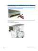
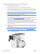
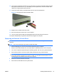
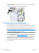
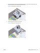
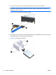
Table Of Contents
- Hardware Upgrades
- Warnings and Cautions
- Additional Information
- Removing the Computer Access Panel
- Replacing the Computer Access Panel
- Removing the Front Bezel
- Removing Bezel Blanks
- Replacing the Front Bezel
- Installing Additional Memory
- Removing or Installing an Expansion Card
- Drive Positions
- Installing Additional Drives
- Battery Replacement
- Installing a Security Lock
- Electrostatic Discharge
- Computer Operating Guidelines, Routine Care and Shipping Preparation
- Index
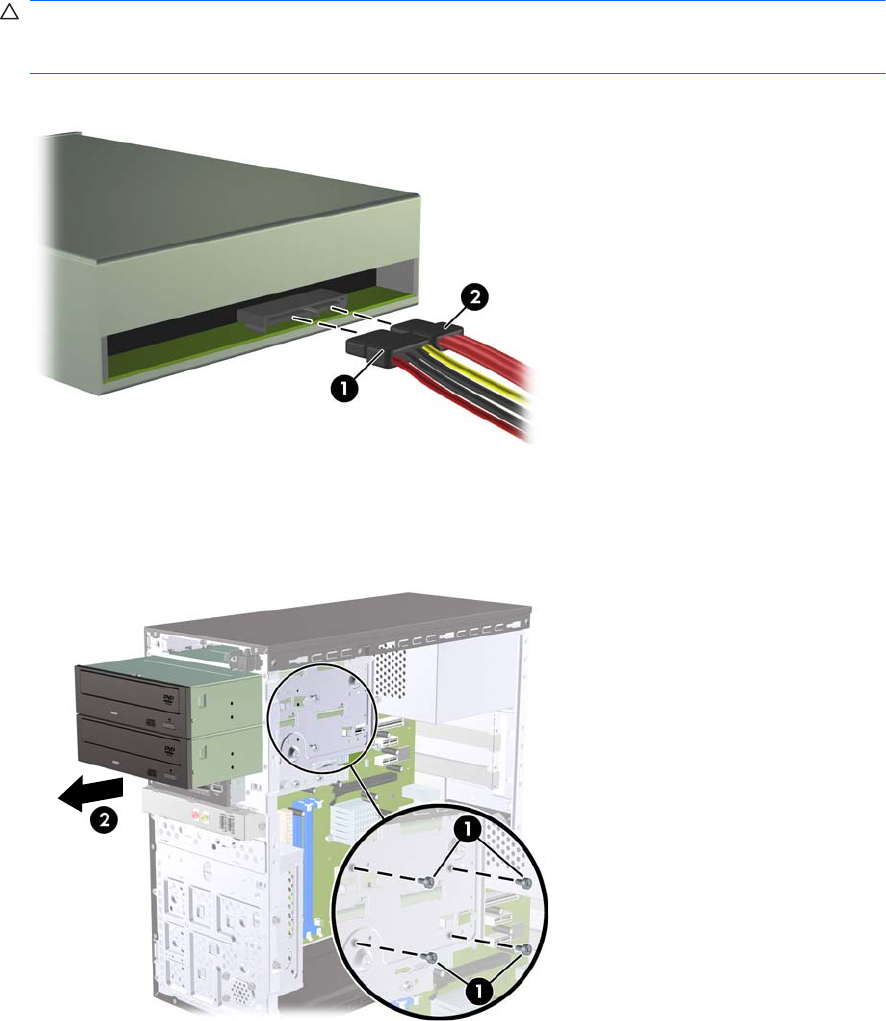
6. Disconnect the power cable (1) and data cable (2) from the rear of the optical drive.
CAUTION: On some models you must press down on the latch on top of the power and data
cables when disconnecting the cables from the drive. Failure to press down on the latch can
damage the cable connectors.
Figure 15 Disconnecting the Power and Data Cables
7. Remove the two screws that secure the drive to the drive cage (1), then slide the drive out of the
front of the chassis (2).
Figure 16 Removing the Optical Drive
ENWW Installing Additional Drives 17