HP Distributed Cloud Networking 3.0.
© Copyright 2014 Hewlett-Packard Development Company, L.P. The information contained herein is subject to change without notice. The only warranties for HP products and services are set forth in the express warranty statements accompanying such products and services. Nothing herein should be construed as constituting an additional warranty. HP shall not be liable for technical or editorial errors or omissions contained herein.
Table of Contents About This Guide...................................................................................................................................... 6 Audience ................................................................................................................................................. 6 1 HP DCN: Overview and Infrastructure............................................................ 7 HP DCN Overview....................................................................
Post-install Security Tasks .......................................................................................................................... 39 4 HP VRS and VRS-G Software Installation....................................................... 42 VRS and VRS-G Installation Overview ........................................................................................................ 42 Preparing the Hypervisor .........................................................................................
Related information ................................................................................................................................. 62 Documentation .................................................................................................................................. 62 Product websites ................................................................................................................................ 62 8 Documentation feedback ....................................
About This Guide The scope of this manual is to describe the installation process for HP Distributed Cloud Networking (DCN). Audience This manual is intended for system administrators who are responsible for installing and configuring the HP DCN software.
1 HP DCN: Overview and Infrastructure This chapter provides an overview of HP Distributed Cloud Networking (DCN) 3.0.R2 and of the infrastructure required to implement the DCN solution. It also gives a brief overview of the installation process itself.
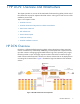
There are three main components in the HP DCN solution: HP Virtualized Services Directory (HP VSD), HP Virtualized Services Controller (HP VSC) and HP Virtual Routing and Switching (HP VRS). HP Virtualized Services Directory HP VSD is a programmable policy and analytics engine that provides a flexible and hierarchical network policy framework that enables IT administrators to define and enforce resource policies.
HP VRS-G For low volume deployments the software based HP VRS Gateway (VRS-G) module incorporates bare metal as virtualized extensions to the datacenter. HP DCN Infrastructure Requirements and Recommendations In order to make use of the HP DCN, the data center environment must meet some key requirements as described in the following sections. Data Center IP Network HP VSP can be used in any data center with an IP network. HP VSC actively participates in the IP routing infrastructure.
Figure 2: Installation Setup Figure 2 diagrams the installation of the HP VSP components and shows how they communicate with each other. The labeled interfaces are referenced in the installation instructions. The diagram could be used to map out the topology you plan to use for your own installation.
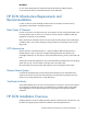
2 HP DCN Software Installation Topics in this chapter include: • HP VSD Hardware and Software Requirements • HP VSD Installation Overview • HP VSD Installation Using QCow2 Image • HP VSD Installation Using ISO Disc Image • Import Certificates on the Servers • Example of Load Balancer Configuration HP VSD Hardware and Software Requirements Installing HP VSD software requires: • A hypervisor of the specifications set out in the Release Notes • A mechanism to access the graphical console of the HP VSD appli
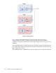
Figure 3: HP VSD 3 + 1 HA Cluster The cluster consists of three HP VSD nodes and one statistics master node (Name node). In addition, a Load Balancer (not supplied) is optional to load balance across the HP VSD nodes for the REST API. Installation Methods The standard method of installation of HP VSD uses the pre-installed appliance. This appliance is distributed in four formats.
mysql -e “update mysql.user set password=PASSWORD WHERE USER=’ROOT’; FLUSH PRIVILEGES;” To change the root password, on each node, run: mysql -uroot -p -e “update mysql.
Consider removing “listen=0.0.0.0” and using an alternative method (for example, virt-manager or SSH tunnel) to obtain console access. hypervisor1server# vsd_name=myh1 hypervisor1server# vsd_disk=/var/lib/libvirt/images/myh1.qcow2 hypervisor1server# virt-install --connect qemu:///system -n $vsd_name -r 24576 --os-type=linux --os-variant=rhel6 --disk path=$vsd_disk,device=disk,bus=virtio,format=qcow2 --vcpus=6 -graphics vnc,listen=0.0.0.
• Connect Via VNC) • Connect Via virsh Console). Connect Via VNC Using a VNC client (e.g. RealVNC, TightVNC) or other console access mechanism, connect to the HP VSD appliance consoles and log in using the default username and password: login: root password: default password Connect Via virsh Console Using a virsh console domain command, connect to the HP VSD appliance consoles and log in using the default username and password.
for example, xmpp.example.com. To use a different host name run the install.sh with the -x option. The DNS server in this example is 10.10.10.100. Test DNS and reverse DNS from each VSD node (VM). 1. Set up the fully qualified names for the nodes in the DNS server forward named file as per the following example: myh1.myd.example.com. 604800 IN A myh2.myd.example.com. 604800 IN A myh3.myd.example.com. 604800 IN A myname.myd.example.com. 604800 IN 192.168.10.101 192.168.10.102 192.168.10.103 A 192.168.10.
Configure NTP Server Include one or more NTP servers in the /etc/ntp.conf file. For example, edit the NTP file and add servers as follows, restarting the NTPD service to put these parameters into effect: server 10.10.0.10 server 192.16.10.10 server 192.16.20.10 Install HP VSD using qcow2 The install script is interactive. Node 1 is the master node, and it serves as a template for the other nodes.
2. Install VSD on Node 2: [root@myh2 ~]# /opt/vsd/install.sh ----------------------------------------------------| V I R T U A L S E R V I C E S D I R E C T O R Y | | (c) 2014 HP Networks | ----------------------------------------------------VSD supports two configurations: 1) HA, consisting of 3 redundant installs of VSD with a cluster name node server. 2) Standalone, where all services are installed on a single machine.
1. Bring up a VM named myh1 using 24 GB RAM and 6 logical cores with the following commands: # vsd_name=myh1 # vsd_disk=/var/lib/libvirt/images/[xxx].qcow2 # virt-install --connect qemu:///system -n $vsd_name -r 24576 --os-type=linux \ --os-variant=rhel6 \ --disk path=$vsd_disk,device=disk,bus=virtio,format=qcow2 \ --vcpus=6 --graphics vnc,listen=0.0.0.0 --noautoconsole --import 2. Repeat this step for each additional hypervisor, naming the additional vsd instances myh2, myh3, and myname.
(default=none): Node 1: myh1.myd.example.com Node 2: myh2.myd.example.com Node 3: myh3.myd.example.com Name Node: myname.myd.example.com XMPP: xmpp.myd.example.com Continue [y|n]? (default=y): y Starting VSD installation. This may take as long as 20 minutes in some situations ... A self-signed certificate has been generated to get you started using VSD. You may import one from a certificate authority later. VSD installed on this host and the services have started. Please install VSD on myh2.myd.example.
• Generate and use a self-signed certificate if you run a proxy: # ./set-cert.sh -r -p proxyHostname Select an option and generate or import the certificate to Node 1. If you are running HA VSD, import it to Nodes 2 and 3 as well. LDAP Store If you are using an LDAP store, see Using an LDAP Store. Example of Load Balancer Configuration frontend vsdha *:443 default_backend vsdhaapp backend vsdhaapp mode tcp balance source server c1 myh1.myd.example.com:8443 check server c2 myh2.myd.example.
3 HP VSC Software Installation This chapter provides installation instructions and the basic configuration for the HP VSC.
• An IP address is already assigned for the management network. • The user has root access to the console of the Linux server. • Either one or three NTP servers have been configured and NTP has synchronized with them. • The user has a means of copying the HP VSC software files to the server. • Two independent network interfaces for management and data traffic, connected to two Linux Bridge interfaces.
3. Enter: cp vsc*disk.qcow2 /var/lib/libvirt/images/ chown qemu:qemu /var/lib/libvirt/images/*.qcow2 For Ubuntu: chown libvirt-qemu:kvm /var/lib/libvirt/images/*.qcow2 4. (Optional) Modify the HP VSC XML configuration to rename the VM or the disk files. 5. Define VM: virsh define vsc.xml 6. Configure VM to autostart: virsh autostart vsc 7. Start the VM: virsh start vsc 8. Connect to the HP VSC console using libvirt: virsh console vsc HP VSC should boot to a login prompt on the console. 9.
Emulated Ethernet NIC Notes Two emulated e1000 Ethernet NICs are required. The HP VSC expects the first NIC to be connected to the management network and the second NIC to be connected to the data network. The recommended configuration is to set up two independent bridges (br## devices in Linux) and attach the emulated NICs and the corresponding physical NICs to each of these bridges. See Appendix: Emulated Ethernet NIC Notes. HP VSC Software Installation Procedure on VMware Starting with VSP 3.
Installing HP VSC on ESXI Using OVA Note: It is presumed that vCenter and ESXi are correctly installed. 1. Enable SSH on the ESX hypervisor. You can do this over the ESX screen or from vCenter. 2. Disable firewall on the ESXi. Run the following CLI on the ESXi host that will run the HP VSC: esxcli network firewall set --enabled false 3. Select the host: 4. Select Edit > Deploy OVF template: 5.
6. Specify a name and location for the deployed template, and then click Next.: 7. Select a resource pool within which to deploy the template, and then click Next.
8. Select the format in which to store the virtual disks, and then click Next. 9. Map the networks used in this OVF template to networks in your inventory (select the port groups), and then click Next. 10. Enter the HP VSC configuration information.
Note: Note that you must enter the control IP addresses of the HP VSC peers in the BGP peer fields.
Then click Next. A summary is displayed. 11. To close the summary, click Finish. 12. Before powering on the VM, add a serial port. Connect via Network, Network Backing to Server, Port URI to telnet://:2500 (this can be any port number). 13. Connect to the serial console of the TIMOS VM using a terminal application, such as PuTTY. 14.
HP VSC Basic Configuration This section describes the intial configuration steps necessary to get the HP VSC up and running and able to communicate with other elements in the VSP. The procedures described include: • HP VSC Boot Options File Configuration • HP VSC System and Protocol Configuration HP VSC Boot Options File Configuration The HP VSC uses a Boot Options File (BOF) named bof.
Table 5: BOF Parameters, Defaults and Descriptions (Continued) Parameter Default Value Description and Notes persist off Specifies whether the system will create a per‐ sistency file (.ndx) which will preserve system indexes (for example, the IP interface MIB object index) across a system reboot. This parameter is typically turned on when the HP VSC is managed with SNMP. ip-address-dhcp no default This optional parameter should be configured in the HP VSC bof.
*A:VSC-1>bof# The management IP address is configured using the address command which has a syntax of: [no] address ip‐prefix/ip‐prefix‐length [active | standby] where keywords are in bold, parameters are in italics and optional elements are enclosed in square brackets. “[ ]”. Typically, the no form of the command will remove the configured parameter or return it to its default value. In the input below, the management IP is set to 192.168.1.254/24: *A:VSC-1>bof# address 192.168.1.254/24 3.
[no] static‐route ip‐prefix/ip‐prefix‐length next‐hop ip‐address Multiple static-route commands can be issued for the Management IP interface. A static route is added for 192.168.100.0/24 with a next hop of 192.168.1.1 with the command below: *A:VSC-1>bof# static-route 192.168.100.0/24 next-hop 192.168.1.1 To check connectivity: ping router “management” 6.
After rebooting, the IP management interface for the HP VSC is configured along with DNS. HP VSC System and Protocol Configuration In addition to the (“out-of-band”) Management IP interface, the HP VSC has an (“in-band”) network interface for the data center’s data network. In order to utilize the in-band network interface and provide connectivity with the other VSP elements, the HP VSC requires some additional system-level configuration as well as in-band data network configuration.
snmp shutdown exit exit all NTP Servers and Time Zone Having the different VSP elements time synchronized with NTP is essential to ensure that the messages passed between the VSD, HP VSC and VRS elements are appropriately timestamped to ensure proper processing. Specify one or more (and preferrably three) NTP servers should be defined like in the example below (10.0.0.123, 10.10.10.18 and 10.200.223.10).
#-------------------------------------------------echo "Virtual Switch Controller Configuration" #-------------------------------------------------exit all configure vswitch-controller xmpp-server "NSC-vPE1:password@xmpp.example.com" open-flow auto-peer 10.9.0.0/24 exit exit xmpp exit exit In-band and Loopback IP Interfaces The excerpt below shows how to configure the in-band interface IP (name control with IP address 10.9.0.7) as well as the loopback (name system with IP address 10.0.0.7) IP interfaces.
#-------------------------------------------------echo "OSPFv2 Configuration" #-------------------------------------------------exit all configure router ospf area 0.0.0.0 interface "system" no shutdown exit interface "control" no shutdown exit exit exit exit exit all BGP needs to be configured if there are multiple HP VSCs that will be operating as a federation.
#-------------------------------------------------echo "BGP Configuration" #-------------------------------------------------exit all configure router bgp connect-retry 2 min-route-advertisement 1 outbound-route-filtering extended-community send-orf exit exit group "internal" type internal neighbor family vpn-ipv4 exit neighbor family evpn exit exit no shutdown exit exit exit all Post-install Security Tasks After installing the HP VSC software, there are a number of tasks that sho
• Secure Unused TCP/UDP Ports After installing and configuring the HP VSC, the user should take all steps necessary to ensure the network security of the HP VSC system through the use of ACLs and/or firewalls and by disabling any unneeded network services on the node. Table 6 lists the required and optional UDP/TCP ports for particular services for inbound connections to the HP VSC. Table 7 lists required and optional UDP/TCP ports for particular services for outbound connections from the HP VSC.
Table 7: HP VSC UDP/TCP Outbound/Remote Ports (Continued) Port UDP/TCP Required/ Optional Protocol Notes 69 UDP Optional TFTP 123 UDP Required NTP 161/162 UDP Optional SNMP ‐ required for SNMP management 179 TCP Required BGP ‐ required for federated HP VSCs 514 UDP Optional Syslog 6633 TCP Required OpenFlow Post-install Security Tasks 41
4 HP VRS and VRS-G Software Installation This chapter provides installation instructions and the basic configuration for HP Virtual Routing and Switching (VRS) and HP Virtual Routing and Switching Gateway (VRS-G).
• The Linux server must be a clean installation with a minimum of configuration and applications. • An IP address must already have been assigned to the server. • DNS must have already been configured and must be operational. • At least two NTP servers must have been configured and NTP must have been synchronized with them. • There must be root access to the console of the Linux server.
yum install perl-JSON yum install qemu-kvm yum install vconfig 3. Install the VRS package for RHEL: tar xzvf 4. Do a yum localinstall of the HP-openvswitch package. 5. Edit /etc/default/openvswitch to achieve the desired VRS configuration. The comments in the file are self-explanatory. Add the VSC controller’s IP addresses: vi /etc/default/openvswitch 6.
Starting openvswitch:Inserting openvswitch module [ OK ] Inserting brcompat module [ OK ] Starting ovsdb-server [ OK ] Configuring Open vSwitch system IDs [ OK ] Configuring Open vSwitch personality [ OK ] Starting ovs-vswitchd [ OK ] Starting ovs-brcompatd [ OK ] OK ] Starting HP monitor:Starting HPMon [ OK Starting vm-monitor:Starting vm-monitor ] [ VRS on Ubuntu 12.04 LTS with Ubuntu 12.04 Cloud Packages The HP-VRS Ubuntu 12.04 .tar.
• hp-openvswitch-common • hp-openvswitch-switch • hp-python-openvswitch Note: Do not install either hp‐openvswitch‐datapath‐dkms (see Installing the VRS Kernel Module for MPLS over GRE) or hp‐metadata‐agent (which is reserved for OpenStack deployments). For OpenStack configuration, refer to the OpenStack deployment guide. Note: dpkg ‐i will not solve dependencies. If you are missing dependencies, install them: apt-get -f install Then run the same dpkg command again. 8.
• Installing VRS Kernel Module On Ubuntu 12.04 Installing VRS Kernel Module On RHEL 1. Install VRS following the instructions in VRS on RHEL. 2. Enable the EPEL repository: rpm -Uvh https://dl.fedoraproject.org/pub/epel/6/x86_64/epel-release-68.noarch.rpm Note: If the EPEL repository install fails, check https://fedoraproject.org/wiki/EPEL for the latest epel‐release package version and location. 3. Install dependencies for DKMS: yum install dkms yum install kernel-devel 4.
Configuring Open vSwitch personality [ OK ] Starting ovs-vswitchd [ OK ] [ OK ] OK ] Starting ovs-brcompatd Starting hp monitor:Starting hpMon Starting vm-monitor:Starting vm-monitor [ OK ] [ Installing VRS Kernel Module On Ubuntu 12.04 1. Install VRS following the instructions in VRS on Ubuntu 12.04 LTS with Ubuntu 12.04 Cloud Packages. 2. Install dependencies for DKMS: apt-get install dkms linux-headers-`uname -r` 3. Reboot to pick up correct kernel: reboot 4.
5 VMware VRS VM Deployment Topics in this chapter include: • Introduction • Prerequisites • Creating the dVSwitch • Verifying the Creation of the dVSwitch • vSphere vSwitch Configurations • Deployment of dVRS • Information Needed • Verifying Deployment Introduction This chapter describes the integration of the Virtual Routing and Switching (VRS) VM with VMware that is required for all VMware deployments with VMware vSphere Hypervisor (ESXi).
• VCENTER_PASSWD • CLUSTER_NAME From the CloudMgmt-vmware package, run the command cli.bash with the following arguments, taking account of the note below. bash# ./cli.
dVswitch This is the dvSwitch we created in Creating the dVSwitch. Note down the name of the port group ending with "-OVSPG", for example, "-OVSPG." "dataNetworkPortgroup":"DVRS Datapath", "mgmtNetworkPortgroup":"Lab Management", "vmNetworkPortgroup":"-OVSPG" Deployment of dVRS Note: If you have a small number of hypervisors, you can manually deploy the OVF Template from the vSphere Client (File > Deploy OVF Template).
bash# ./cli.bash deploy_vrs -m -f --url https:///sdk -u -p Deployment of dVRS Verify that a resource group "HP System Resources" is created on each cluster. Verify that there is one dVRS VM created for each hypervisor in the cluster. Additional Verification Log in to the the DVRS VM (with username/password: root/UFXCr4733F) and execute the command "ovs‐vsctl show.
6 VRS Installation on Citrix XenServer 6.2 This document describes the method for installing and upgrading VRS on Citrix XenServer 6.2. Note: HP VRS cannot be installed on the following: • XenServers without HP OVS controllers • XenServer versions prior to 6.
Introduction Block 1 Installation 1. Remove stock openvswitch Note: rpm -qa | grep openvswitch All rpms must be removed: 'yum remove' is recommended. 2. Have ready the hp xen dVRS, which consists of the following rpms: • hp-openvswitch- • hp-openvswitch-modules-xen-2.6.32.43-0.4.1.xs1.8.0.835.170778- 3. Install in the following order a. rpm -i HP-openvswitch-modules-xen-2.6.32.43-0.4.1.xs1.8.0.835.170778 b.
Block 2 Installation Reboot XenServer. Verification After the XenServer comes up, in addition to the usual verification such as interface status, management network connectivity etc., perform the following verification checks: 1. Ensure that the bridge corresponding to HPManagedNetwork does not have any PIF attached to it. [root@acs-ovs-3 ~]# ovs-vsctl show 016cccd2-9b63-46e1-85d1-f27eb9cf5e90 ~Snip~ Bridge "xapi0" Controller "ctrl1" target: "tcp:10.10.14.
[root@ovs-2 ~]# ps aux | grep -i HP root 5482 0.0 0.0 3484 388 ? S< 15:18 0:00 HPMon: monitoring pid 5483 (healthy) root 5483 0.0 0.0 3488 544 ? S
Block 1 Installation 1. Have ready the HP xen dVRS, which consists of the following rpms: • hp-openvswitch- • hp-openvswitch-modules-xen-2.6.32.43-0.4.1.xs1.8.0.835.170778- 2. Install in the following order: a. rpm -U hp-openvswitch-modules-xen-2.6.32.43-0.4.1.xs1.8.0.835.170778 b. rpm -U hp-openvswitch- Verification 1. Ensure that all packages are installed: [root@ovs-2 images]# rpm -qa | grep openvswitch hp-openvswitch-modules-xen-2.6.32.43-0.4.1.xs1.8.0.835.
[root@acs-ovs-3 ~]# ovs-vsctl show 016cccd2-9b63-46e1-85d1-f27eb9cf5e90 ~Snip~ Bridge "xapi0" Controller "ctrl1" target: "tcp:10.10.14.8:6633" role: slave fail_mode: standalone Port "xapi0" Interface "xapi0" type: internal Bridge "xenbr0" fail_mode: standalone Port "eth0" Interface "eth0" Port "xenbr0" Interface "xenbr0" type: internal Bridge "xenbr2" ~Snip~ 2.
grep -i hp [root@ovs-2 ~]# 4. Ensure that the xenmon to OVS socket is up: [root@ovs-2 ~]# netstat -na | grep vm unix 2 [ ACC ] STREAM LISTENING openvswitch/vm-events.ctl unix 3 [ ] STREAM CONNECTED openvswitch/vm-events.ctl [root@ovs-2 ~]# 12972 /var/run/ 59425 /var/run/ Running and Configuring VRS The HP startup script takes care of starting all the components as well as the basic configuration of VRS, which is primarily the assignment of OpenFlow controller(s) to that bridge.
VRS Installation on Citrix XenServer 6.
7 Support and Other Resources To learn how to contact HP, obtain software updates, submit feedback on documentation, and locate links to HP SDN websites and other related HP products, see the following topics.
• For information about licenses for the controller, see the HP VAN SDN Controller Administrator Guide. • For information about licenses for HP SDN applications, see the information about licensing in the administrator guide for the application. Care Packs To supplement the technical support provided with the purchase of a license, HP offers a wide variety of Care Packs that provide full technical support at 9x5 or 24x7 availability with annual or multi-year options.
• Primary website: http://www.hp.com/go/sdn • Development center: http://www.sdndevcenter.hp.com • User community forum: http://www.hp.com/networking/sdnforum • HP Open Source Download Site: http://www.hp.com/software/opensource • HP Networking services website: http://www.hp.
Support and Other Resources
8 Documentation feedback HP is committed to providing documentation that meets your needs. To help us improve the documentation, send any errors, suggestions, or comments to Documentation Feedback (docsfeedback@hp.com). Include the document title and part number, version number, or the URL when submitting your feedback.
9 Appendix: Emulated Ethernet NIC Notes A hypervisor hosting a VSC VM is expected to have two bridge interfaces used to attach the VSC management and datapath NICs. This appendix shows an example configuration for the bridge interfaces and associated NICs. In the procedure and sample output below, eth0 is associated with br0, and eth1 is associated with br1. The Ethernet to bridge mappings can be customized according to your hardware and network configuration.
TYPE="Ethernet" Edit (or create) the br0 configuration Edit the file /etc/sysconfig/network-scripts/ifcfg-br0 to match the information below, replacing the IP address and netmask as appropriate: DEVICE="br0" TYPE="Bridge" ONBOOT="yes" BOOTPROTO="static" IPADDR=" 192.0.2.10" NETMASK="255.255.255.0" GATEWAY=" 192.0.2.