
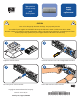
Power Supply Hardware Component Replacement Instructions

10
11
7
8
9
5
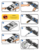
Pull the module from the slot.
Push the module into the slot.
Pull out both levers on new module.
CAUTION
DO NOT leave slot empty for
more that 2 minutes.
PORT1
FC-AL100MB/s
PORT0 PORT1
ADDRESS
4
3
2
1
0
6
5
FC-AL100MB/s FC-AL100MB/s
LINK
ACTIVE
LINK
ACTIVE
LCC
ACTIVE
LCC
FAULT
A6214-60001
6
Push in both cam levers at the same time.
Tighten the cam lever screws with a straight blade screwdriver.
Re-connect power cord.
Green LED indicates power supply is functioning.