Hardware Reference Guide - dc7900 Series Convertible Minitower HP Compaq Business PC
© Copyright 2008 Hewlett-Packard Development Company, L.P. The information contained herein is subject to change without notice. Microsoft, Windows, and Windows Vista are either trademarks or registered trademarks of Microsoft Corporation in the United States and/or other countries. The only warranties for HP products and services are set forth in the express warranty statements accompanying such products and services. Nothing herein should be construed as constituting an additional warranty.
About This Book This guide provides basic information for upgrading this computer model. WARNING! Text set off in this manner indicates that failure to follow directions could result in bodily harm or loss of life. CAUTION: Text set off in this manner indicates that failure to follow directions could result in damage to equipment or loss of information. NOTE: Text set off in this manner provides important supplemental information.
iv About This Book ENWW
Table of contents 1 Product Features Standard Configuration Features ......................................................................................................... 1 Front Panel Components ..................................................................................................................... 2 Media Card Reader Components ......................................................................................................... 3 Rear Panel Components ................................
Changing from a Desktop to a MinitowerConfiguration ...................................................................... 45 Appendix A Specifications Appendix B Battery Replacement Appendix C External Security Devices Installing a Security Lock .................................................................................................................... 53 Cable Lock ......................................................................................................................... 53 Padlock .
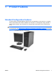
1 Product Features Standard Configuration Features The HP Compaq Convertible Minitower features may vary depending on the model. For a complete listing of the hardware and software installed in the computer, run the diagnostic utility (included on some computer models only). Instructions for using the utility are provided in the Troubleshooting Guide. NOTE: The HP Compaq Convertible Minitower computer can be easily converted to a desktop.
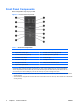
Front Panel Components Drive configuration may vary by model. Figure 1-2 Front Panel Components Table 1-1 Front Panel Components 1 5.25-inch Optical Drives 8 5.25-inch Bay for Optional Drives2 2 Optical Drive Activity Lights 9 Diskette Drive Activity Light (optional) 3 3.
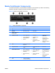
Media Card Reader Components The media card reader is an optional device available on some models only. Refer to the following illustration and table to identify the media card reader components. Figure 1-3 Media Card Reader Components Table 1-2 Media Card Reader Components No.
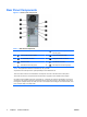
Rear Panel Components Figure 1-4 Rear Panel Components Table 1-3 Rear Panel Components 1 Power Cord Connector 6 Line-Out Connector for powered audio devices (green) 2 Line-In Audio Connector (blue) 7 Universal Serial Bus (USB) 3 RJ-45 Network Connector 8 DisplayPort Monitor Connector 4 Serial Connector 9 VGA Monitor Connector 5 PS/2 Mouse Connector (green) 10 PS/2 Keyboard Connector (purple) NOTE: Arrangement and number of connectors may vary by model.
Keyboard Figure 1-5 Keyboard Components Table 1-4 Keyboard Components 1 ENWW 1 Function Keys Perform special functions depending on the software application being used. 2 Editing Keys Includes the following: Insert, Home, Page Up, Delete, End, and Page Down. 3 Status Lights Indicate the status of the computer and keyboard settings (Num Lock, Caps Lock, and Scroll Lock). 4 Numeric Keys Work like a calculator keypad. 5 Arrow Keys Used to navigate through a document or Web site.
Using the Windows Logo Key Use the Windows Logo key in combination with other keys to perform certain functions available in the Windows operating system. Refer to Keyboard on page 5 to identify the Windows Logo key. Table 1-5 Windows Logo Key Functions The following Windows Logo Key functions are available in Microsoft Windows XP and Microsoft Windows Vista.
Serial Number Location Each computer has a unique serial number and a product ID number that are located on the top cover of the computer. Keep these numbers available for use when contacting customer service for assistance.
2 Hardware Upgrades Serviceability Features The computer includes features that make it easy to upgrade and service. No tools are needed for most of the installation procedures described in this chapter. Warnings and Cautions Before performing upgrades be sure to carefully read all of the applicable instructions, cautions, and warnings in this guide.
Unlocking the Smart Cover Lock NOTE: The Smart Cover Lock is an optional feature included on some models only. The Smart Cover Lock is a software-controllable cover lock, controlled by the setup password. This lock prevents unauthorized access to the internal components. The computer ships with the Smart Cover Lock in the unlocked position. For more information about locking the Smart Cover Lock, refer to the Desktop Management Guide.
5. Use the Smart Cover FailSafe Key to remove the two tamper-proof screws that secure the Smart Cover Lock to the chassis. Figure 2-1 Removing the Smart Cover Lock Screws You can now remove the access panel. See Removing the Computer Access Panel on page 11. To reattach the Smart Cover Lock, secure the lock in place with the tamper-proof screws.
Removing the Computer Access Panel 1. Remove/disengage any security devices that prohibit opening the computer. 2. Remove all removable media, such as diskettes or compact discs, from the computer. 3. Turn off the computer properly through the operating system, then turn off any external devices. 4. Disconnect the power cord from the power outlet and disconnect any external devices.
Replacing the Computer Access Panel 1. Lay the computer down on its large base for greater stability. 2. Align the tabs on the access panel with the slots on the chassis and push down on the access panel while sliding it forward until it locks into place.
Removing the Front Bezel 1. Remove/disengage any security devices that prohibit opening the computer. 2. Remove all removable media, such as diskettes or compact discs, from the computer. 3. Turn off the computer properly through the operating system, then turn off any external devices. 4. Disconnect the power cord from the power outlet and disconnect any external devices.
Replacing the Front Bezel 1. Place the bottom hinge points on the front bezel in their corresponding slots in the chassis (1). 2. Rotate the front bezel onto the chassis (2). 3. Snap the catches at the top of the bezel into place (3). 4. Snap the release tabs into place (4).
Removing Bezel Blanks 1. Remove/disengage any security devices that prohibit opening the computer. 2. Remove all removable media, such as diskettes or compact discs, from the computer. 3. Turn off the computer properly through the operating system, then turn off any external devices. 4. Disconnect the power cord from the power outlet and disconnect any external devices.
Installing Additional Memory The computer comes with double data rate 2 synchronous dynamic random access memory (DDR2SDRAM) dual inline memory modules (DIMMs). DIMMs The memory sockets on the system board can be populated with up to four industry-standard DIMMs. These memory sockets are populated with at least one preinstalled DIMM. To achieve the maximum memory support, you can populate the system board with up to 16-GB of memory configured in a highperforming dual channel mode.
Populating DIMM Sockets There are four DIMM sockets on the system board, with two sockets per channel. The sockets are labeled DIMM1, DIMM2, DIMM3, and DIMM4. Sockets DIMM1 and DIMM2 operate in memory channel A. Sockets DIMM3 and DIMM4 operate in memory channel B.
and the remainder is assigned to single channel. For optimal speed, the channels should be balanced so that the largest amount of memory is spread between the two channels. If one channel will have more memory than the other, the larger amount should be assigned to Channel A. For example, if you are populating the sockets with one 1-GB DIMM, and three 512-MB DIMMs, Channel A should be populated with the 1-GB DIMM and one 512-MB DIMM, and Channel B should be populated with the two 512-MB DIMMs.
7. Open both latches of the memory module socket (1), and insert the memory module into the socket (2). Figure 2-8 Installing a DIMM NOTE: A memory module can be installed in only one way. Match the notch on the module with the tab on the memory socket. A DIMM must occupy the black DIMM1 socket. For maximum performance, populate the sockets so that the memory capacity is spread as equally as possible between Channel A and Channel B. Refer to Populating DIMM Sockets on page 17 for more information. 8.
Removing or Installing an Expansion Card The computer has three standard full-height PCI expansion slots, one PCI Express x1 expansion slot, one PCI Express x16 expansion slot, and one PCI Express x16 expansion slot that is downshifted to a x4 slot.
CAUTION: Regardless of the power-on state, voltage is always present on the system board as long as the system is plugged into an active AC outlet. You must disconnect the power cord to avoid damage to the internal components of the computer. 5. Remove the computer access panel. 6. Locate the correct vacant expansion socket on the system board and the corresponding expansion slot on the back of the computer chassis. 7.
NOTE: Before removing an installed expansion card, disconnect any cables that may be attached to the expansion card. a. If you are installing an expansion card in a vacant socket, remove the appropriate expansion slot cover on the back of the chassis. Lift the expansion slot cover from the expansion slot. Figure 2-11 Removing an Expansion Slot Cover b. If you are removing a standard PCI card, hold the card at each end and carefully rock it back and forth until the connectors pull free from the socket.
c. If you are removing a PCI Express x16 card, pull the retention arm on the back of the expansion socket away from the card and carefully rock the card back and forth until the connectors pull free from the socket. Lift the card straight up to remove it. Be sure not to scrape the card against other components. Figure 2-13 Removing a PCI Express x16 Expansion Card 9. Store the removed card in anti-static packaging. 10.
11. To install a new expansion card, slide the bracket on the end of the card down into the slot on the back of the chassis and press the card down firmly into the socket on the system board. Figure 2-14 Installing an Expansion Card NOTE: When installing an expansion card, press firmly on the card so that the whole connector seats properly in the expansion card slot. 12. Close the expansion card retention latch, making sure that it snaps firmly into place. 13.
Drive Positions Figure 2-15 Desktop and Minitower Drive Positions Table 2-3 Drive Positions 1 1 Three 5.25-inch external drive bays for optional drives (optical drives shown)1 2 One 3.5-inch external drive bay for optional drives (diskette drive shown)2 3 Two 3.5-inch internal hard drive bays An optional media card reader and an optional hard drive mounting bracket for these drive bays are available from HP. The bottom 5.25-inch drive bay has a shorter depth than the upper two bays.
Removing a Drive from a Drive Bay CAUTION: All removable media should be taken out of a drive before removing the drive from the computer. 1. Remove/disengage any security devices that prohibit opening the computer. 2. Remove all removable media, such as diskettes or compact discs, from the computer. 3. Turn off the computer properly through the operating system, then turn off any external devices. 4. Disconnect the power cord from the power outlet and disconnect any external devices.
● If you are removing a diskette drive, disconnect the data cable (1) and power cable (2) from the back of the drive.
● If you are removing a media card reader, disconnect the USB cable from the system board. If the media card reader has a 1394 port, disconnect the 1394 cable from the PCI card.
7. Remove the drive from the drive bay as follows: ● To remove a 5.25-inch drive in the desktop configuration, press down on the yellow drivelock mechanism (1) and slide the drive from the drive bay (2). CAUTION: When the yellow drivelock is pressed, all the external 5.25-inch drives are released so do not tilt the unit and allow the drives to fall out. Figure 2-20 Removing a 5.25-inch Drive in the Desktop Configuration (Optical Drive shown) ● To remove a 3.5-inch drive or a 5.
● To remove a hard drive from and internal 3.5-inch drive bay, pull up on the green hard drive drivelock mechanism (1) for that drive and slide the drive from the drive bay (2). Figure 2-22 Removing a Hard Drive 8. 30 Store the removed drive in anti-static packaging.
Installing Additional Drives The computer supports up to five drives that may be installed in various configurations. When installing additional drives, follow these guidelines: ● The primary Serial ATA (SATA) hard drive must be connected to the dark blue SATA connector on the system board labeled SATA0. ● Connect the first SATA optical drive to the white SATA connector on the system board labeled SATA1.
Figure 2-24 Extra Optical Drive M3 Guide Screws Location CAUTION: To prevent loss of work and damage to the computer or drive: If you are inserting or removing a drive, shut down the operating system properly, turn off the computer, and unplug the power cord. Do not remove a drive while the computer is on or in standby mode. Before handling a drive, ensure that you are discharged of static electricity. While handling a drive, avoid touching the connector.
System Board Drive Connections Refer to the following illustration and table to identify the system board drive connectors. Figure 2-25 System Board Drive Connections Table 2-4 System Board Drive Connections ENWW No.
Installing a 5.25-inch or 3.5-inch Drive into an External Drive Bay NOTE: A 3.5-inch drive may be a diskette drive or a media card reader. A 5.25-inch drive may be an optical drive or a media card reader with a 5.25-inch adapter kit attached. 1. Remove/disengage any security devices that prohibit opening the computer. 2. Remove all removable media, such as diskettes or compact discs, from the computer. 3. Turn off the computer properly through the operating system, then turn off any external devices.
8. Install the drive in the desired drive bay by sliding it all the way into the front of the drive cage until it locks (2). The drivelock automatically secures the drive in the bay. CAUTION: The bottom 5.25-inch drive bay has a shorter depth than the upper two bays. The bottom bay supports a half-height drive or other device that is no more than 14.5 cm (5.7 inches) in depth. Do not try to force a larger drive, such as an optical drive, into the bottom bay.
Installing a 3.5-inch SATA Hard Drive into an Internal Drive Bay NOTE: The system does not support Parallel ATA (PATA) hard drives. Before you remove the old hard drive, be sure to back up the data from the old hard drive so that you can transfer the data to the new hard drive. Also, if you are replacing the primary hard drive, make sure you have created a Recovery Disc Set to restore the operating system, software drivers, and any software applications that were preinstalled on the computer.
7. Slide the hard drive down into the drive cage until it locks. The drivelock automatically secures the drive in the bay. Figure 2-29 Installing a Hard Drive into the Hard Drive Bay CAUTION: Make sure the guide screws line up with the guide slots in the drive cage. The use of unnecessary force when installing any drive into the drive bay may result in damage to the drive. 8. Connect the power cable (1) and data cable (2) to the rear of the hard drive.
12. Lock any security devices that were disengaged when the computer access panel was removed. 13. Reconfigure the computer, if necessary. Refer to the Computer Setup (F10) Utility Guide for instructions on using Computer Setup. Removing and Replacing a Removable 3.5-inch SATA Hard Drive Some models are equipped with a Removable SATA Hard Drive Enclosure in the 5.25-inch external drive bay. The hard drive is housed in a carrier that can be quickly and easily removed from the drive bay.
3. Remove the adhesive strip that secures the thermal sensor to the top of the hard drive (1) and move the thermal sensor away from the carrier (2). Figure 2-32 Removing the Thermal Sensor 4. Remove the four screws from the bottom of the hard drive carrier.
5. Slide the hard drive back to disconnect it from the carrier then lift it up and out of the carrier. Figure 2-34 Removing the Hard Drive 6. Place the new hard drive in the carrier then slide the hard drive back so that it seats in the SATA connector on the carrier's circuit board. Be sure the connector on the hard drive is pressed all the way into the connector on the carrier's circuit board.
7. Replace the four screws in the bottom of the carrier to hold the drive securely in place. Figure 2-36 Replacing the Security Screws 8. Place the thermal sensor on top of the hard drive in a position that does not cover the label (1) and attach the thermal sensor to the top of the hard drive with the adhesive strip (2).
9. Slide the cover on the carrier (1) and replace the screw on the rear of the carrier to secure the cover in place (2). Figure 2-38 Replacing the Carrier Cover 10. Slide the hard drive carrier into the enclosure on the computer and lock it with the key provided. NOTE: The carrier must be locked for power to be supplied to the hard drive.
Changing from a Minitower to a Desktop Configuration 1. Remove/disengage any security devices that prohibit opening the computer. 2. Remove all removable media, such as diskettes or compact discs, from the computer. 3. Turn off the computer properly through the operating system, then turn off any external devices. 4. Disconnect the power cord from the power outlet and disconnect any external devices.
9. Before you reinstall each drive into the chassis, turn the drive so that it is perpendicular to the internal 3.5-inch drive. The drive should be parallel to the green latch drive bracket. Figure 2-40 Installing a Drive in the Desktop Configuration 10. Gently slide the drive into the uppermost available bay until it snaps into place. When the drive is properly inserted, the drivelock will secure it. Repeat this step for each drive. CAUTION: The bottom 5.
14. Reposition the subpanel (rotate it 90º) with the logo at the bottom, then snap it back into the bezel. Figure 2-41 Changing from a Minitower to a Desktop Configuration 15. Replace the front bezel and computer access panel. 16. Reconnect the power cord and turn on the computer. 17. Lock any security devices that were disengaged when the computer access panel was removed. Changing from a Desktop to a MinitowerConfiguration 1. Remove/disengage any security devices that prohibit opening the computer. 2.
8. To release the drives from the 5.25-inch drive bay, press down on the short yellow drivelock as shown. While pressing the drivelock, pull the drives out of the drive bay. Figure 2-42 Releasing the 5.25-inch Drives from the Drive Bays (Desktop) 9. Before you reinstall each drive into the chassis, turn it so that it is in the same orientation as the internal 3.5-inch drive. The bottom of the drive should be parallel to the yellow drivelock.
11. Reconnect all power and data cables to the drives in the 5.25-inch drive bays. 12. Remove the bezel subpanel as described in the Removing Bezel Blanks on page 15 section. CAUTION: Hold the subpanel straight when you pull it away from the front bezel. Pulling the subpanel away at an angle could damage the pins that align it within the front bezel. 13. Reposition the bezel blanks within the subpanel in the proper orientation for the minitower configuration. 14.
A Specifications Table A-1 Specifications Desktop Dimensions Height 7.0 in 17.8 cm Width 17.63 in 44.8 cm Depth 17.8 in 45.2 cm Height 17.63 in 44.8 cm Width 7.0 in 17.8 cm Depth 17.8 in 45.2 cm Approximate Weight 26.4 lb 12.0 kg Weight Supported (maximum distributed load in desktop position) 77 lb 35 kg Operating 50° to 95°F 10° to 35°C Nonoperating -22° to 140°F -30° to 60°C Tower Dimensions Temperature Range NOTE: Operating temperature is derated 1.
Table A-1 Specifications (continued) Power Supply 115V 230V Operating Voltage Range1 90-264 VAC 90-264 VAC Rated Voltage Range 100-240 VAC 100-240 VAC Rated Line Frequency 50-60 Hz 50-60 Hz Power Output 365 W 365 W Standard PS 6A @ 100 VAC 3A @ 200 VAC 85% Efficient PS 5A @ 100VAC 2.5A @ 200VAC Rated Input Current (maximum)1 1 This system utilizes an active power factor corrected power supply.
B Battery Replacement The battery that comes with the computer provides power to the real-time clock. When replacing the battery, use a battery equivalent to the battery originally installed in the computer. The computer comes with a 3-volt lithium coin cell battery. WARNING! The computer contains an internal lithium manganese dioxide battery. There is a risk of fire and burns if the battery is not handled properly. To reduce the risk of personal injury: Do not attempt to recharge the battery.
NOTE: On some computer models, it may be necessary to remove an internal component to gain access to the battery. 7. Depending on the type of battery holder on the system board, complete the following instructions to replace the battery. Type 1 a. Lift the battery out of its holder. Figure B-1 Removing a Coin Cell Battery (Type 1) b. Slide the replacement battery into position, positive side up. The battery holder automatically secures the battery in the proper position. Type 2 a.
b. Insert the new battery and position the clip back into place. Figure B-3 Removing a Coin Cell Battery (Type 3) NOTE: After the battery has been replaced, use the following steps to complete this procedure. 8. Replace the computer access panel. 9. Plug in the computer and turn on power to the computer. 10. Reset the date and time, your passwords, and any special system setups using Computer Setup. Refer to the Computer Setup (F10) Utility Guide. 11.
C External Security Devices NOTE: For information on data security features, refer to the Computer Setup (F10) Utility Guide, the Desktop Management Guide, and the HP ProtectTools Security Manager Guide (some models) at http://www.hp.com. Installing a Security Lock The security locks displayed below and on the following page can be used to secure the computer.
Padlock Figure C-2 Installing a Padlock 54 Appendix C External Security Devices ENWW
HP Business PC Security Lock 1. Fasten the security cable by looping it around a stationary object. Figure C-3 Securing the Cable to a Fixed Object 2. Thread the keyboard and mouse cables through the lock.
3. Screw the lock to the chassis using the screw provided. Figure C-5 Attaching the Lock to the Chassis 4. Insert the plug end of the security cable into the lock (1) and push the button in (2) to engage the lock. Use the key provided to disengage the lock.
D Electrostatic Discharge A discharge of static electricity from a finger or other conductor may damage system boards or other static-sensitive devices. This type of damage may reduce the life expectancy of the device. Preventing Electrostatic Damage To prevent electrostatic damage, observe the following precautions: ● Avoid hand contact by transporting and storing products in static-safe containers.
E Computer Operating Guidelines, Routine Care and Shipping Preparation Computer Operating Guidelines and Routine Care Follow these guidelines to properly set up and care for the computer and monitor: 58 ● Keep the computer away from excessive moisture, direct sunlight, and extremes of heat and cold. ● Operate the computer on a sturdy, level surface. Leave a 10.2-cm (4-inch) clearance on all vented sides of the computer and above the monitor to permit the required airflow.
Optical Drive Precautions Be sure to observe the following guidelines while operating or cleaning the optical drive. Operation ● Do not move the drive during operation. This may cause it to malfunction during reading. ● Avoid exposing the drive to sudden changes in temperature, as condensation may form inside the unit. If the temperature suddenly changes while the drive is on, wait at least one hour before you turn off the power. If you operate the unit immediately, it may malfunction while reading.
Index A access panel locking and unlocking removing 11 replacing 12 audio connectors 2, 4 B battery replacement 9, 53 50 C changing computer configuration 43, 45 computer operating guidelines 58 connecting drive cables 31 D desktop conversion 43 DIMMs.
R rear panel components 4 removable hard drive replacing 38 removing battery 50 bezel blanks 15 computer access panel 11 drives from drive bay 26 expansion card 20 expansion slot cover 22 front bezel 13 media card reader 26 PCI card 22 PCI Express card 23 Smart Cover Lock 9 S security cable lock 53 HP Business PC Security Lock 55 padlock 54 Smart Cover Lock 9 serial connector 4 serial number location 7 shipping preparation 59 Smart Cover Lock 9 specifications computer 48 memory 16 system board drive connect