HP Data Center Environmental Edge Hardware Installation Guide Abstract This document is for the person who installs, administers, and troubleshoots HP Data Center Environmental Edge systems.
© Copyright 2009, 2011 Hewlett-Packard Development Company, L.P. The information contained herein is subject to change without notice. The only warranties for HP products and services are set forth in the express warranty statements accompanying such products and services. Nothing herein should be construed as constituting an additional warranty. HP shall not be liable for technical or editorial errors or omissions contained herein. Confidential computer software.
Contents HP Data Center Environmental Edge hardware overview ................................................................... 5 Recommended base configuration ............................................................................................................... 5 Required tools ........................................................................................................................................... 6 HP Environmental Edge Installer Kit ...........................................
Verifying Verifying Verifying Verifying Verifying gateway communication ................................................................................................... 72 network settings ............................................................................................................... 73 HP Water Leak Detection Base Station functionality .............................................................. 74 ION power meter communication .........................................................
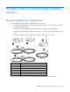
HP Data Center Environmental Edge hardware overview Recommended base configuration HP recommends the following base configuration for your data center: • Two Base Station Gateways for every 400 base stations (A minimum of one base station gateway is required per wireless network.
Required tools The following items are required for installation: • HP Environmental Edge Installer Kit • Ladder • Floor tile suction lifter • Perforated floor tile lifter • Battery-operated label maker with: o Spare batteries o Spare ribbon • USB barcode scanner • Small wire cutting pliers • 18-30 AWG wire strippers • No.
HP Base Station Gateway Overview: Gateway The gateway collects information from all wireless base stations within a wireless network and sends the information to the HP Insight Environmental Observer software over an Ethernet connection. Only one instance of the HP Insight Environmental Observer software can connect to a gateway device, though it can connect to multiple gateways within the data center, depending on the available network connection.
3. Configure the IP address of the computer to a temporary static address such as 192.168.0.10. NOTE: You only need to set the IP address to a static address of the configuring computer during the configuration of the gateway. When you complete the configuration, restore your original network settings. 4. Open your web browser, and in the URL address box, type in the default gateway address: http://192.168.0.2 The Lantronix Web Manager Login window appears. 5.
o The default password is PASS.
6. In the navigation menu on left side of the page, select Network. The Network Configuration page appears. NOTE: The Ethernet link settings of speed and duplex must match the settings of the switch and servers NIC. If the speeds or duplex do not match, then the gateway cannot communicate with the Edge server. 7. Populate the following fields, using the same information you entered in the HP Insight Environmental Configurator: o IP address (Example: 10.100.100.30) o Network mask (Example: 255.255.254.
o Device Status page HP Base Station Gateway 11
o Line 1 Configuration page HP Base Station Gateway 12
o Tunnel 1 Serial Settings page HP Base Station Gateway 13
o Tunnel 1 Accept Mode page HP Base Station Gateway 14
o Tunnel 1 Connect Mode page HP Base Station Gateway 15
10. In the navigation menu on the left side of the page, select System. The System page appears. 11. Select Reboot. The confirmation window appears. 12. Select OK. The gateway reboots, and the new configured parameters take effect. 13. Repeat steps 1 through 11 for all gateways, using each unique IP address used in the HP Insight Environmental Configurator. 14. Restore the original network settings on your computer.
3. Insert and tighten the antenna to the gateway. 4. Remove the mounting tape liner, and secure the gateway to the desired location. 5. Connect one end of the supplied power cable to the gateway and the other end to a power source.
6. Connect one end of the CAT5 Ethernet cable to the gateway and the other end to your network. 7. Turn on the gateway by flipping the power switch. 8. Verify that the gateway is connected to power and is working in operation mode by viewing the gateway LED status (on page 18). o Connected—The gateway Active LED is either flashing or solid green and the Battery LED is off. o Not connected—The gateway Battery LED is either flashing or solid red. Installation is complete.
o • Is solid red if the gateway is not connected to the network or if HP Insight Environmental Observer application is not running. Active LED o Flashes green if the gateway is communicating and active. o Is solid green is the gateway is connected properly and is working in operating mode.
HP Environmental Base Station installed on a rack Overview: Installing a base station on a rack The base station is a wireless device that collects temperature data from the external sensor arrays and sends the information to the gateway. The base station has its own internal temperature and humidity sensors and collects data to send to the gateway. When the base station is installed on a rack, it is attached to either the HP Rack Sensor Array or the HP Three Point Sensor Array.
o The HP Rack Sensor Array has the Front (Cold) Side label and the Rear (Hot) Side label, indicating where the sensor string is installed. o The HP Three Point Sensor Array does not have a label and can be installed anywhere on the rack or in the data center. NOTE: The preconfigured lengths between the sensor pods are designed to fit a standard 42U rack and should be evenly spaced: one at the top of the rack door, one in the middle of the rack door, and one at the bottom of the rack door.
5. Remove the mounting tape liner and attach the cable restraint brackets near the door hinges on the rack. NOTE: The disconnect connector on the sensor array enables you to remove the rack door for maintenance without having to uninstall the HP Environmental Base Station. 6. Using a cable tie wrap, secure any excess cabling. 7. If you are installing the HP Rack Sensor Array, repeat the previous steps for the rear door.
NOTE: You can install the base station outside or inside of the top of the rack. 1. Ensure the area on the top of the rack is free from dust before installing the base station. 2. Remove the mounting tape liner, and secure the base station to the desired location on the top of the rack. 3. Connect the data transfer cable from the HP Rack Sensor Array or HP Three Point Sensor Array to the base station. 4. After all hardware is installed, power up the components ("Power up procedure" on page 70).
Installation is complete.
HP Environmental Base Station installed on a CRAH/CRAC Overview: Installing a base station on a CRAH/CRAC The base station is a wireless device that collects temperature data from the external sensor arrays and sends the information to the gateway. The base station also has its own internal temperature and humidity sensors and collects data of its own to send to the gateway.
2. Verify that you are installing the correct sensor string to the correct location in the CRAH/CRAC. The CRAH Supply side is routed to the supply side of the CRAH/CRAC, and the CRAH Return side is routed to the return side of the CRAH/CRAC. 3. Route and install the supply sensor. HP recommends installing the supply sensor to a support beam under the sub-floor in front of the CRAH/CRAC. Consult your data center administrator for the exact location for installation. a.
HP recommends using cable tie wraps to secure the base station to an available support bracket. 2. Connect the data transfer cable from the HP Plenum Rated Sensor Array to the base station. 3. After all hardware is installed, power up the components ("Power up procedure" on page 70). Installation is complete.
Callout Component Description and humidity. Installing the HP Environmental CRAH/CRAC (Dual) Base Station The CRAH/CRAC (Dual) Base Station consists of: • One base station for the supply air—Measures the supply air temperature and humidity • One base station for the return air—Measures the return air temperature (the average of the six sensors on the array) and humidity Installing the HP Environmental Base Station in the supply air stream 1.
WARNING: The CRAH/CRAC must be powered down and the fans must be stopped before you access the return plenum for hardware installation. 1. Ensure the desired installation locations around the CRAH/CRAC are free of dust before installing the sensor array. NOTE: During installation of a CRAH/CRAC (dual) base station, ignore the Supply and Return labels on the sensor array. All six sensors are installed in the return air stream. 2.
Dual CRAH installation diagram Callout Component Description 1 CRAH return air stream The return air side of the CRAH 2 CRAH supply air stream The supply air side of the CRAH 3 CRAH supply base station The base station is mounted on the supply air side of the CRAH, and measures the supply air temperature and humidity.
HP Air Pressure Base Station Overview: Air Pressure Base Station The air pressure base station is a wireless device that monitors the differential pressure across areas of the data center and sends the information to the gateway. The air pressure base station monitors and compares the difference between the pressure below the floor and the pressure above the floor. Installing the HP Air Pressure Base Station 1. Determine the location for the air pressure base station in your data center. 2.
c. Route the air tube to the area below the floor that you want to monitor. d. Use cable tie wraps to secure the air tube to a support bracket below the floor. 6. Install the short air tube. This tube monitors the reference pressure above the floor. a. Attach a flag label indicating the negative terminal to the short air tube. b. Insert the short air tube into the negative terminal on the air pressure base station. The air tube sits above the floor.
o 8. If there is a location behind and under a rack near subfloor access, use the double-sided mounting tape to secure the air pressure base station to the floor tile near the subfloor access. After all hardware is installed, power up the components ("Power up procedure" on page 70). Installation is complete.
(Optional) Sensor Base Stations Overview: (Optional) Sensor base stations The optional sensor base stations enable HP approved third-party components to communicate wirelessly to the gateways. The sensor base stations are considered optional depending on whether you want to monitor other environmental data in your data center. The connection between the data center component and the supplied sensor might require professional installation.
2. Remove the mounting tape liner, and secure the base station to the desired location on the top of the rack. 3. Remove the mounting tape liner, and secure the door position wire harness to the rack door. 4. Connect the Door Position Base Station to the door sensors. a. Strip the plastic coating from the ends of the two door sensor wires. b. Strip the plastic coating from the ends of the two wires on the Door Position Base Station wire harness.
d. Insert the connector from the Door Position Base Station wire harness into the Door Position Base Station. 5. After all hardware is installed, power up the components ("Power up procedure" on page 70). Installation is complete. Installing the HP Chilled Water Energy Base Station The HP Chilled Water Energy Base Station connects to the housing box, which contains an ultrasonic probe sensor. The ultrasonic sensor measures and reports liquid flow through a chilled water pipe.
b. If a support bracket is available, use cable ties to secure the housing box to the support bracket. 2. Route the ultrasonic probe to the appropriate locations along the chilled water pipe. 3. Connect the housing box to the required sources.
Single Chilled Water installation diagram Callout Component 1 Chilled Water Energy Base Station 2 Water supply line to the CRAH/CRAC 3 Water return line from the CRAH/CRAC 4 Water supply temperature sensor probe 5 Upstream flow meter 6 Water return temperature sensor probe 7 Downstream flow meter Configuring the Chilled Water Base Station NOTE: You must have the ULTRALINK™ software installed on the PC that is configuring the base station.
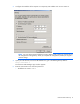
1. Connect a USB connector from the PC to the USB configuration port on the inside of the Chilled Water Base Station. The PC must have the Dynasonic ULTRALINK™ software installed. 2. Open the ULTRALINK™ program. 3. When the program prompts you for a COM Port, enter the appropriate Windows®-assigned USB COM Port. To locate your COM Port, see the Device Manager screen in your Windows® operating system. 4.
If a red OFFLINE error appears, select Communications>Initialize, and then re-enter the appropriate COM port.
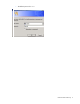
5. To configure the Chilled Water Base Station, select Configuration. The System Configuration window appears. 6. Select the Basic tab, and configure the following parameters: o General—Select the units for the display. o Transducer—Select the type, mount, and frequency of the transducer. o Pipe—Select the material, diameter, and wall thickness of the pipe. o Liner—If a liner is used, select the material and thickness.
o 7. Fluid—Select the type of water. Select the Flow tab, and configure the following parameters: o Flow rate units—Select the measurement rates. o Totalizer units—Select the measurement rates. o Min flow—Select the minimum flow rate. o Max flow—Select the maximum flow rate.
8. Select the Output tab, and configure the following parameters: o Module #1—Select the volumetric flow and energy transmitted to the console. o Flow at 4mA (Min flow)—Select the minimum flow rate. This must match the parameters set on the Flow tab.
o Flow at 20mA (Max flow)—Select the maximum flow rate. This must match the parameters set on the Flow tab.
9. Select the Basic tab, and then select Download to transfer the new settings into the Chilled Water Base Station. 10. Select OK to save the configuration settings and close the System Configuration window. Testing the configuration The 4mA and 20mA calibration values are factory set and must not be modified. If you modify these calibration values and select Download, you will override the 4-20mA factory preset. You can test the analog flow meter output for troubleshooting purposes.
The flow at 4mA is 0 l/s and the flow at 20mA is 30 l/s. If the Test field is set to 4, then the flow rate on the console must be 0 l/s. If the Test field is set to 20, then the flow rate on the console must be 30 l/s. Installing the HP Water Leak Detector Base Station The HP Water Leak Detector Base Station connects to the supplied leak detector sensor and detects and reports the presence of any fluid along the sensing cable. To install the Water Leak Detector Base Station: 1.
2. If a support bracket is available, use cable ties to secure both the base station (1) and the water leak detector (2) to the support bracket. 3. Connect the leak detector sensing cable assembly to the Water Leak Detector. a. Cut approximately 5-cm (2-inch) of wire from the end of the wire harness. b. Strip the plastic coating from the ends of the wire you just cut to create a jumper wire. c. Strip the plastic coating from the two wire pairs on the wire harness. d.
k. Replace the Water Leak Detector lid, and use the supplied Allen wrench to tighten the two screws to secure the lid. Callout Component Description 1 5VDC IN Insert the white wire into the + (positive) terminal. Insert the black wire into the - (negative) terminal. 2 Fault and Leak 3 W terminal Insert the white wire from the wire harness. 4 B terminal Insert the black wire from the wire harness. 5 G terminal Insert the green wire from the wire harness.
Water Leak Detector installation diagram Callout Component Description 1 AC adapter Plugs into a power source 2 Base station Wirelessly transmits information to the Edge server 3 Connection point Connects the base station to the water leak detector 4 Water leak detector Processes the detection of fluid 5 Connection point Connects the water leak detector to the jumper cable 6 Jumper cable Connects the sensing cable to the water leak detector 7 Connector Connects the jumper cable to th
a. If a flat surface is available, remove the mounting tape liner and secure the base station to the surface. b. If a support bracket is available, use cable ties to secure the base station to the support bracket. 2. Connect the Current Sensing Relay Base Station to your current sensor. a. Strip the plastic coating from the ends of the two wires on the wire harness labeled CH 3. b. Using a flathead screwdriver, secure the white wire to the positive terminal block on the current sensor transducer.
c. Using a flathead screwdriver, secure the black wire to the negative terminal block on the current sensor transducer. d. Insert the connector from the wire harness into the Current Sensing Relay Base Station. 3. Connect one end of the 24V AC adapter to the power input connector on the base station, and then plug the other end of the AC adapter into a power source. The base station automatically powers up and follows the Base Station LED sequence.
a. If a flat surface is available, remove the mounting tape liner and secure the base station to the surface. b. If a support bracket is available, use cable ties to secure the base station to the support bracket. 2. Connect the 200A Current Base Station to your current sensor. a. Strip the plastic coating from the ends of the two wires on the wire harness labeled CH 3/Current A. b. Using a flathead screwdriver, secure the white wire to the positive terminal block on the current sensor transducer.
c. Using a flathead screwdriver, secure the black wire to the negative terminal block on the current sensor transducer. Repeat for the other two current transducers (CH 4 and CH 5/Current B and Current C). d. Insert the connector from the wire harness into the 200A Current Base Station. 3. Connect one end of the 24V AC adapter to the power input connector on the 200A Current Base Station, and then plug the other end of the AC adapter into a power source.
Installation is complete.
1. Choose the location for the Energy Base Station, relative to your energy meter. 2. Connect the Energy Base Station to your energy meter. a. Strip the plastic coating from the ends of the two wires on the Energy Base Station wire harness. b. Open the energy meter. c. Using a small screwdriver, loosen the 1K and COM terminals. d. Insert the end of the red wire into the 1K terminal. e. Insert the end of the black wire into the COM terminal. f.
o RS-485 (-): Pin 4 (RJ-45 connector) to Pin 3 (RS-232 connector) Callout Component Description 1 RJ-45 Ethernet connector Component of the Modbus adapter 2 RS-232 connector Component of the Modbus adapter 3 A/C power connector Connects to the power source 4 CAT5 Ethernet connector Connects to the network 5 Modbus adapter (RJ-45 to Connects the RJ-45 connector to the RS-232 connector RS-232) RS-485 cable Connects the energy meter to the Modbus base station 6 5.
Energy Base Station installation diagram Callout Component Description 1 Energy meter Energy meter(with housing case removed) you want to measure 2 RS-485 (+ terminal) RS-485 (+) 3 RS-485 (- terminal) RS-485 (-) 4 RS-485 (ground/shield) RS-485 (ground wire) 5 RS-485 bus terminating resistor If a single energy meter is connected to the Modbus base station, the terminating resistor must be installed.
4. Press and hold the UP and DOWN arrows simultaneously for a minimum of 2 seconds to exit. Programming the voltage mode Set the Volts Mode type according to the specific power connection type. Power connection type ION setting 4wire wye (4 wire, 3 phases + neutral) 4W Direct Delta (3 wire, 3 phases, no neutral) dELd Programming the CT model NOTE: All of the CTs must have the same ratings.
• Ct1 = 200 • Ct2 = 5 Programming the digital out 1. Set the following values. Digital out ION setting out1 wh 0.5 Tc1 NOTE: You cannot verify the CT polarity if you are in the Direct Delta voltage mode. To verify the CT polarity, temporarily switch the meter to 4W mode. After the polarity is verified, switch back to dELd mode. For more information, see Programming the voltage mode (on page 58). 2. Verify the CT polarity by reading the current phase values.
2. Set the device unit ID to a number value between 1 and 32. If multiple meters are connected in a daisy chain series, each meter must have a unique device unit ID. NOTE: The baud rate you set on the ION Energy Meter Modbus ID ("Programming the Modbus ID" on page 59) must match the baud rate you set in the Modbus Base Station configuration ("Configuring the Modbus Base Station" on page 61). 3. Set the serial baud rate to 19.2K.
4. Set the power scale (PPS) to 10x. Configuring the Modbus Base Station 1. Go to the Comtrol website (http://www.comtrol.com), download and install Port Vision Plus software. Port Vision Plus software is used to locate, configure, and manage DeviceMasters over a network. 2. Select the Scan button to discover the Modbus base station.
The Scan results appear. 3. Right-click the Modbus base station you want to configure and select Web Manager.
The main Comtrol Web Manager main page appears. 4. Configure the device network settings.
a. From the main page, select Configure Network. The Edit Network Configuration page appears. b. Enter the IP address properties, as provided by the network administrator. c. 5. Select Save. Configure device serial settings.
a. From the main page, select Serial Device Configuration. The Serial Device Configuration page appears.
b. Select Port 1 to change the serial port settings. c. On the Mode menu, select RS-485. NOTE: The baud rate you set on the ION Energy Meter Modbus ID ("Programming the Modbus ID" on page 59) must match the baud rate you set in the Modbus Base Station configuration ("Configuring the Modbus Base Station" on page 61). d. On the Baud menu, select the appropriate baud rate. If multiple meters are connected in a daisy chain series, each meter must use the same baud rate. 6. Configure the Ethernet Device.
a. From the main page, select Ethernet Device Configuration. The Ethernet Device Configuration page appears.
b. Select Socket 1. The Edit Socket Port 1 Configuration page appears.
7. From the main page, select Reboot to update all new configurations.
Power up procedure Powering up the components 1. Verify that the gateway is connected to the power and is working in operation mode by viewing the gateway LED status (on page 18). o Connected—The gateway Active LED is either flashing or solid green and the Battery LED is off. o Not connected—The gateway Battery LED is either flashing or solid red. NOTE: The gateway must be active before powering up the base stations. 2.
1. During the initial power up mode and after the initial bootup LED sequence, the LED on the base station flashes red while attempting to find and connect to the gateway. 2. When the base station is connected, the LED flashes green indicating that it is communicating with the gateway. 3. When the base station is identified by the gateway, it stops flashing and begins working in operating mode. The LED on the base station is off. The initial power up mode only lasts approximately 5 to 10 minutes.
Troubleshooting HP Insight Environmental troubleshooting tips To troubleshoot communication issues: 1. Turn off all of the wireless base stations in the data center. 2. Power cycle each of the wireless gateways ("Power cycle the wireless gateways" on page 72). 3. From the server, turn off the HP Insight Environmental Device Manager component. 4. Verify that each of the gateways are communicating ("Verifying gateway communication" on page 72). 5.
Use the following flow chart to help troubleshoot gateway communication errors and determine whether you must replace the gateway. Verifying network settings You must set network and Ethernet settings in three separate locations.
• Network card on the Edge server • Network switch between the Edge server and the gateway Verifying HP Water Leak Detection Base Station functionality When verifying the functionality of the water leak detector base station, the LED status must match the status reported in the Observer software.
Verifying the CT shorting block position If the CT values for your ION power meter all appear to be zero, a CT shorting block might be in the down (installation) position. Verify that all of the shorting blocks are in the up (operating) position.
Regulatory compliance notices Wireless devices You can install one or more integrated wireless devices. In some environments, the use of wireless devices might be restricted. Such restrictions might apply on airplanes, in hospitals, near explosives, or in other hazardous locations. Before you turn on this product, be sure that you understand local policies and have proper authorization. Do not co-locate or operate this device in conjunction with any other antenna or transmitter.
European Union regulatory notice Products bearing the CE marking comply with the following EU Directives: • Low Voltage Directive 2006/95/EC • EMC Directive 2004/108/EC • Ecodesign Directive 2009/125/EC, where applicable CE compliance of this product is valid if powered with the correct CE-marked AC adapter provided by HP.
The point of contact for regulatory matters is Hewlett-Packard GmbH, Dept./MS: HQ-TRE, Herrenberger Strasse 140, 71034 Boeblingen, GERMANY. Brazilian notices Este equipamento opera em caráter secundário, isto é, não tem direito a proteção contra interferência prejudicial, mesmo de estações do mesmo tipo, e não pode causar interferência a sistemas operando em caráter primário.
For more information about battery replacement or proper disposal, contact an authorized reseller or an authorized service provider. Taiwan battery recycling notice The Taiwan EPA requires dry battery manufacturing or importing firms in accordance with Article 15 of the Waste Disposal Act to indicate the recovery marks on the batteries used in sales, giveaway or promotion. Contact a qualified Taiwanese recycler for proper battery disposal.
Acronyms and abbreviations CRAC computer room air conditioning CRAH computer room air handler CT current transducer LED light-emitting diode PDU power distribution unit Acronyms and abbreviations 80
Index A G air pressure base station, installation 31 air pressure base station, overview 31 gateway, communication 72 gateway, configuring 7 gateway, installing 16 gateway, LED status 18 gateway, overview 7 gateway, power cycle 72 B base configuration 5 base station, CRAH/CRAC overview 25 base station, dual CRAH/CRAC installation 28, 30 base station, LED status 70 base station, rack installation 20 base station, rack overview 20 base station, single CRAH/CRAC installation 25, 27 battery disposal 78 Braz
M wireless devices 76, 78 Modbus Base Station, configuring 61 modifications, FCC notice 76 N network settings 73 notices 2 O overview 5 P power cycle gateways 72 power meter, programming 57, 58, 59 power up procedure 70 powering up the components 70 programming the power meter 57, 58, 59 programming, CT model 58 programming, digital out 59 programming, Modbus communication 59 programming, Modbus ID 59 programming, voltage mode 58 R recommended configuration 5 regulatory compliance notices 76 required