
Getting Started Guide


2-4
Detailed Hardware Installation and Initial Setup Steps
Overview
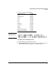
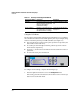
Table 2-1. Summary of Cable Types to Use with the DCM Controller
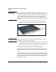
■ Installation Location—Before installing the DCM Controller, plan its
location and orientation relative to other devices and equipment.
• In the front of the DCM Controller, leave at least 7.6 cm (3 inches) of
space for the twisted-pair cabling.
• In the back of the DCM Controller, leave at least 3.8 cm (1 1/2 inches)
of space for the power cord.
• On the sides of the DCM Controller, leave at least 7.6 cm (3 inches)
for cooling, except if the controller is installed in an open EIA/TIA
rack.
3. Read and Follow the Installation Precautions
Follow these precautions when installing the DCM Controller.
Warning ■ The rack or cabinet should be adequately secured to prevent it from
becoming unstable and/or falling over.
DCM Controllers that are installed in a rack or cabinet should be mounted
as low as possible, with the heaviest devices at the bottom and progres-
sively lighter devices installed above.
■ For safe operation, only install the DCM Controller horizontally, with the
bottom side down.
Port Type Cable Type Length Limits
10/100/1000Base-T For either 10, 100, or 1000 Mbps operation,
Category 5 or better, 100-ohm unshielded
twisted-pair (UTP) or shielded twisted-pair
(STP) balanced cable.
For 1000 Mbps (gigabit) operation, Category
5E cabling or better is recommended.
100 meters
Note: The DCM Controller is compatible with
the IEEE 802.3ab standard including the Auto
MDI/MDI-X feature, which allows use of
either straight-through or crossover twisted-
pair cables for connecting to any network
devices, including end nodes, such as
computers, switches, hubs, and routers.
Note: For 1000 Mbps operation, all four wire
pairs are used for data transmission.