HP ProCurve Datacenter Connection Manager Controller Hardware Installation and Getting Started Guide
02-Front.fm Page ii Monday, April 13, 2009 5:46 PM © Copyright 2009, 2012, Hewlett-Packard Development Company, L.P. The information contained herein is subject to change without�notice. All Rights Reserved. This document contains proprietary information, which is protected by copyright. No part of this document may be photocopied, reproduced, or translated into another language without the prior written consent of Hewlett-Packard.
1 Hardware Overview and Quick Start Installation and Initial Setup Contents HP ProCurve Datacenter Connection Manager Controller . . . . . . . . . . . . . 1-2 Hardware . . . . . . . . . . . . . . . . . . . . . . . . . . . . . . . . . . . . . . . . . . . . . . . . . . . . . . 1-5 Hardware Specifications . . . . . . . . . . . . . . . . . . . . . . . . . . . . . . . . . . . . . 1-5 Physical Dimensions . . . . . . . . . . . . . . . . . . . . . . . . . . . . . . . . . . . . . 1-5 Electrical . . . . . . . . . . .
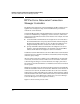
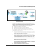
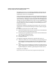
Hardware Overview and Quick Start Installation and Initial Setup HP ProCurve Datacenter Connection Manager Controller HP ProCurve Datacenter Connection Manager Controller The HP ProCurve Datacenter Connection Manager (DCM) Controller is a 1U appliance that is designed to help network administrators provision the network for server interfaces.
Hardware Overview and Quick Start Installation and Initial Setup HP ProCurve Datacenter Connection Manager Controller Figure 1-1.
Hardware Overview and Quick Start Installation and Initial Setup HP ProCurve Datacenter Connection Manager Controller This simple process can occur seamlessly, eliminating waiting periods and possible frustration because of miscommunications between the network administrator and the server administrator. DCM Controller also provides a framework for collecting information that can be useful to network administrators.
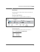
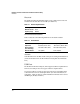
Hardware Overview and Quick Start Installation and Initial Setup Hardware Hardware This section provides the DCM Controller’s hardware specifications and describes its LEDs. Hardware Specifications The DCM Controller is a 1U appliance (J9445A). (See Figure 1-2.) Figure 1-2. Front Panel of the DCM Controller Physical Dimensions The exact dimensions of the DCM Controller are listed in Table 1-1. Table 1-1. Physical Dimensions of the DCM Controller Width 44.3 cm (17.42 in) Depth 39 cm (15.
Hardware Overview and Quick Start Installation and Initial Setup Hardware Electrical The DCM Controller automatically adjusts to any voltage between 100–127 and 200–240 volts and either 50 or 60 Hz. (See Table 1-2.) Table 1-2. Electrical Specifications AC voltage 100–127/200–240 volts Maximum current 2A/1A Frequency range 50/60 Hz Environmental Guidelines Table 1-3 lists the environmental guidelines for the DCM Controller. Table 1-3.
Hardware Overview and Quick Start Installation and Initial Setup Hardware Ethernet Ports The DCM Controller has two 10/100/1000 Base-T RJ-45 ports labeled: ■ 1 (left port) ■ 2 (right port) Only port 1 is active at this time. This port supports the following standards: ■ IEEE 802.3ab 1000Base-T ■ IEEE 802.3u 100Base-TX ■ IEEE 802.3 10Base-T Safety DCM Controller complies with the following: ■ EN60950-1 / IEC 60950-1 ■ CSA 22.2 No.
Hardware Overview and Quick Start Installation and Initial Setup Hardware ■ ■ Speed LED—indicates the connection speed: • Off—10 Mbps • Green—100 Mbps • Orange—1000 Mbps Eth/Act LED—indicates the status of the Ethernet link Console Port The console port is located beneath the front panel LEDs and enables out-ofband management. The port accepts an RJ45 connector; use the RJ45 Connector/Console Cable (5188-6699) that ships with your DCM Controller.
Hardware Overview and Quick Start Installation and Initial Setup Hardware Press the accept button to access the panel LCD menu interface and complete tasks such as: ■ Configuring IP settings ■ Testing connectivity ■ Rebooting and shutting down the DCM Controller Serial Number and MAC Address A label on the front panel of the DCM Controller displays the device’s serial number and its MAC address.
Hardware Overview and Quick Start Installation and Initial Setup Warranty and Support Warranty and Support HP ProCurve Networking provides a one-year warranty for the DCM Controller. To register for this warranty, visit the My ProCurve Portal (https://my.procurve.com). ProCurve provides support through email and telephone during HP’s local business hours.
Hardware Overview and Quick Start Installation and Initial Setup Quick Start Hardware Installation and Initial Setup Quick Start Hardware Installation and Initial Setup This section is designed to help you install the DCM Controller and access its management interface as quickly as possible. It provides just the basic hardware installation and setup steps for network administrators who have some experience installing network devices and configuring Linux-based systems.
Hardware Overview and Quick Start Installation and Initial Setup Quick Start Hardware Installation and Initial Setup Determine the exact location where the DCM Controller will be installed and gather the network cable you will use to connect the controller to the network. (For detailed instructions, see “2. Prepare the Installation Site” on page 2-3 in Chapter 2: “Detailed Hardware Installation and Initial Setup Steps.”) Warning 3. Read and follow the installation precautions outlined below.
Hardware Overview and Quick Start Installation and Initial Setup Quick Start Hardware Installation and Initial Setup 5. Connect power to the DCM Controller. After the DCM Controller is mounted, plug it into the nearby main power source. (For more information, see “5. Connect the DCM Controller to a Power Source” on page 2-7 in Chapter 2: “Detailed Hardware Installation and Initial Setup Steps.”) 6. Connect the network cables.
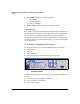
Hardware Overview and Quick Start Installation and Initial Setup Quick Start Hardware Installation and Initial Setup Figure 1-5. Panel LCD Menu > Configuration c. Select IP Address—Port 1. Figure 1-6. Panel LCD Menu > Configuration > IP Address—Port 1 d. Set the DCM Controller’s IP address. Use the left and right arrow buttons to move the cursor from digit to digit. Use the up and down arrow buttons to alter the selected digit. Figure 1-7.
Hardware Overview and Quick Start Installation and Initial Setup Quick Start Hardware Installation and Initial Setup Figure 1-9. Panel LCD Menu > Configuration > IP Address—Port 1 (Gateway) h. Set the IP address of the DCM Controller’s default gateway. By default, the DCM Controller sets the default gateway to the lowest IP address in its subnet. If necessary, use the arrow buttons to change the address. Then, press the accept button. The DCM Controller operating system checks the new IP settings.
Hardware Overview and Quick Start Installation and Initial Setup Quick Start Hardware Installation and Initial Setup Figure 1-11. Panel LCD Menu > Ping Test iv. Enter the IP address that you want to ping. By default, the IP address is set to the DCM Controller’s default gateway. Press the accept button to ping the default gateway. To ping a different IP address, use the left and right arrow buttons to move the cursor from digit to digit. Use the up and down arrow buttons to alter the selected digit.
Hardware Overview and Quick Start Installation and Initial Setup Quick Start Hardware Installation and Initial Setup Figure 1-13. Establishing a Console Connection to Access the Root b. Use the following credentials to log in: – Username: root – Root password: procurve The following prompt is displayed: ProCurve DCM(localhost):~# Caution When you log in as root, you have all rights to the DCM Controller’s operating system.
Hardware Overview and Quick Start Installation and Initial Setup Quick Start Hardware Installation and Initial Setup 9. Specify the RADIUS clients. Using vi or another text editor, edit the /etc/raddb/clients.conf file to include the switches that will use the DCM Controller’s RADIUS service. For each client, include the IP address and the shared secret, which must match the secret configured on the switch. a. Enter: vi /etc/raddb/clients.conf b. Locate the Client line.
Hardware Overview and Quick Start Installation and Initial Setup Quick Start Hardware Installation and Initial Setup The DCM Controller’s Login window is displayed: Figure 1-14. The Login Window for the Web Browser Interface c. Enter manager as the user name and procurve as the password and click the Login button. Next Steps To begin provisioning your network for servers, refer to the HP ProCurve Datacenter Connection Manager Controller Management and Configuration Guide.
Hardware Overview and Quick Start Installation and Initial Setup Quick Start Hardware Installation and Initial Setup 1-20
2 Detailed Hardware Installation and Initial Setup Steps Contents Overview . . . . . . . . . . . . . . . . . . . . . . . . . . . . . . . . . . . . . . . . . . . . . . . . . . . . . . 2-2 1. Ensure That You Have All the Parts . . . . . . . . . . . . . . . . . . . . . . . . . . 2-2 2. Prepare the Installation Site . . . . . . . . . . . . . . . . . . . . . . . . . . . . . . . . 2-3 3. Read and Follow the Installation Precautions . . . . . . . . . . . . . . . . . 2-4 4. Mount the Unit . . . . . . . . . . . . .
Detailed Hardware Installation and Initial Setup Steps Overview Overview This chapter provides detailed step-by-step instructions for: ■ Installing the HP ProCurve Datacenter Connection Manager (DCM) Controller ■ Completing the initial setup For additional configuration information about the DCM Controller, see: ■ HP ProCurve Datacenter Connection Manager Controller Management and Configuration Guide—designed for network administrators who must configure network infrastructure devices to support serve
Detailed Hardware Installation and Initial Setup Steps Overview ■ Power cord, one of the following: Australia/New Zealand 8121-0838 China 8121-0910 Continental Europe 8120-8861 Denmark 8120-8930 India 8121-0780 Israel 8121-1035 Japan 8120-4753 Switzerland 8121-0908 South Africa 8120-8929 Taiwan 8121-0974 Thailand 8121-0673 United Kingdom/Hong Kong 8121-0909 United States/Canada/Mexico 8121-0921 Japan Power Cord Warning 2.
Detailed Hardware Installation and Initial Setup Steps Overview Table 2-1. Summary of Cable Types to Use with the DCM Controller Port Type Cable Type Length Limits 10/100/1000Base-T For either 10, 100, or 1000 Mbps operation, Category 5 or better, 100-ohm unshielded twisted-pair (UTP) or shielded twisted-pair (STP) balanced cable. 100 meters For 1000 Mbps (gigabit) operation, Category 5E cabling or better is recommended. Note: The DCM Controller is compatible with the IEEE 802.
Detailed Hardware Installation and Initial Setup Steps Overview Cautions ■ Ensure that the power source circuits are properly grounded and use the power cord supplied with the DCM Controller to connect it to the power source. ■ If your installation requires a different power cord than the one supplied with the unit, be sure to use a power cord displaying the mark of the safety agency that defines the regulations for power cords in your country.
Detailed Hardware Installation and Initial Setup Steps Overview Equipment Cabinet Note The 12-24 screws supplied with the DCM Controller are the correct threading for standard EIA/TIA open 19-inch racks. If you are installing the DCM Controller in an equipment cabinet such as a server cabinet, use the clips and screws that came with the cabinet in place of the 12-24 screws that are supplied with the controller.
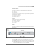
Detailed Hardware Installation and Initial Setup Steps Overview Caution Make sure the air flow is not restricted around the sides and back of the DCM Controller. 5. Connect the DCM Controller to a Power Source Plug the included power cord into the DCM Controller’s power connector on the back panel and into a nearby AC power source. Figure 2-2. DCM Controller, Rear View with Power Plug 6.
Detailed Hardware Installation and Initial Setup Steps Overview Table 2-2. Summary of IP Configuration Methods Configuration Method Description LCD menu Locate the LCD menu on the front “Using the LCD Menu” on page panel and press the configuration 2-8 buttons to set the DCM Controller’s IP settings. Instructions Console Interface Establish a console session and use a simply menu to configure the DCM Controller’s IP settings.
Detailed Hardware Installation and Initial Setup Steps Overview Figure 2-5. Panel LCD Menu > Configuration 2. Select IP Address—Port 1. Figure 2-6. Panel LCD Menu > Configuration > IP Address—Port 1 3. Set the DCM Controller’s IP address. a. Use the left and right arrow buttons to move the cursor from digit to digit. Then use the up and down arrow buttons to alter the selected digit. Note that the DCM Controller treats each set of three digits as a single number.
Detailed Hardware Installation and Initial Setup Steps Overview b. When you are finished, press the accept button. Figure 2-8. Panel LCD Menu > Configuration > IP Address—Port 1 (Subnet Mask) 4. Set the DCM Controller’s subnet mask. a. Use the arrow buttons to alter the subnet mask. b. Press the accept button when you are finished. Figure 2-9. Panel LCD Menu > Configuration > IP Address—Port 1 (Gateway) 5. Set the IP address of the DCM Controller’s default gateway.
Detailed Hardware Installation and Initial Setup Steps Overview 6. Verify connectivity by pinging: • The DCM Controller’s default gateway • Your management station a. Access the main LCD menu. Press the accept button to access the main menu initially; press the cancel button to move back a screen. Figure 2-10. Panel LCD Main Menu b. Select Ping Test. Figure 2-11. Panel LCD Menu > Ping Test c. Set the IP address to which you want to confirm connectivity.
Detailed Hardware Installation and Initial Setup Steps Overview Using the Console Interface The DCM Controller has an easy-to-use console interface for performing basic initial setup tasks such as: ■ Configuring IP settings ■ Changing the DCM Controller admin password to control access to the console interface 1. To access the console interface, connect the serial cable provided to a PC or VT-100 terminal. Figure 2-13. Establishing a Console Connection to Access the Console Menu 2. 3.
Detailed Hardware Installation and Initial Setup Steps Overview Note The admin username gives you access to the Application Main Menu from which you can configure IP settings. Later in the initial setup process, you will establish a console session and enter root as the username. The root username grants you all rights to the DCM Controller’s operating system. (When you use root access, you must be extremely careful not to misconfigure the operating system so that it malfunctions.
Detailed Hardware Installation and Initial Setup Steps Overview Figure 2-15. Configuring IP Address in the Console Interface 5. At the IP address prompt, enter an IP address in standard IP notation and press Enter. IP address (default 192.168.0.2): Optionally, you can accept the default IP address in parentheses by pressing Enter without typing an IP address. 6. At the Subnet mask prompt, enter the subnet mask in standard IP notation and press Enter. Subnet mask (default 255.255.255.
Detailed Hardware Installation and Initial Setup Steps Overview 9. Press y to confirm that you want to make these changes and then press Enter. 10. Press 0 to return to the Main Menu. 11. Press 0 to log out of the console interface. 12. After you set the IP address, you should verify connectivity by pinging: • The DCM Controller’s default gateway • Your management station a. Access the console menu and press 2 for Diagnostics. b. Press 1. Ping Test. Figure 2-16.
Detailed Hardware Installation and Initial Setup Steps Overview Figure 2-17. Ping Test Output Showing a Successful Test d. To ping a different IP address, press Enter to return to the Diagnostics menu, and then repeat the steps to send a ping. e. When you are finished, press Enter and 0 to return to the Main Menu. f. Exit the console interface. 8.
Detailed Hardware Installation and Initial Setup Steps Overview Figure 2-18. Establishing a Console Connection to Access the Root CLI 2. Use the following credentials to log in: • Username: root • Root password: procurve The following prompt is displayed: ProCurve DCM(localhost):~# Caution When you log in as root, you have all rights to the DCM Controller’s operating system. Be extremely careful: misconfigurations can cause the DCM Controller to malfunction.
Detailed Hardware Installation and Initial Setup Steps Overview 9. Specify the RADIUS Clients You must now specify the RADIUS clients—the network switches—that will use the DCM Controller to authenticate the server interfaces. Using vi or another text editor, edit the /etc/raddb/clients.conf file to include each client, its IP address, and the shared secret (which must match the secret configured on the switch).
Detailed Hardware Installation and Initial Setup Steps Overview 2. Enter https://:8181/dcmWeb as the URL. Replace with the IP address that you configured for the DCM Controller. You might need to accept a certificate exception. The DCM Controller’s Login window is displayed: Figure 2-19. The Login Window for the Web Browser Interface 3. Enter manager as the user name and procurve as the password and click the Login button.
Detailed Hardware Installation and Initial Setup Steps Overview 2-20
A Back up, Restore, and Re-initialize the HP Datacenter Connection Manager (DCM) Controller Backing Up and Restoring DCM Controller Data You should back up your configuration and data regularly in case of network or appliance failure. You can then restore the configuration and data, if it becomes necessary, keeping your structure of pods, connection classes, and connections intact. DCM Controller includes scripts for completing the backup and restore process.
Back up, Restore, and Re-initialize the HP Datacenter Connection Manager (DCM) Controller Backing Up and Restoring DCM Controller Data Caution Be very careful when entering commands from the root: misconfigurations can cause the device to malfunction. You should be experienced with Linux systems before using these commands. Note These steps instruct you to back up your data onto a USB drive. However, you can also back up the data to any safe network location that DCM Controller can reach.
Back up, Restore, and Re-initialize the HP Datacenter Connection Manager (DCM) Controller Backing Up and Restoring DCM Controller Data 6. Allow the process to execute. You should then see a confirmation message such as the following: SUCCESS: File [location]backup-bundle-Feb-20-0911047.log added Process ended ProCurve DCM(mydcm):~# The message confirms that the backup script executed successfully and that a log file named backup-bundle-[Mmm-dd-yy-nnnnn].
Back up, Restore, and Re-initialize the HP Datacenter Connection Manager (DCM) Controller Backing Up and Restoring DCM Controller Data Caution Be very careful when entering commands from the root: misconfigurations can cause the device to malfunction. You should be experienced with Linux systems before using these commands. 4. If you specified a network location in the backup script command, skip to step 6.
Back up, Restore, and Re-initialize the HP Datacenter Connection Manager (DCM) Controller Recovering DCM Controller The default destination location for the output file is var/tmp/. You may specify a different destination path. This command creates a .tar file named support-bundle-MMM-DD-YYnnnnnnn.tar. It also creates a .log file that tells the user which files and data were successfully added to the bundle and which were not and some additional information about the possible causes. The .
Back up, Restore, and Re-initialize the HP Datacenter Connection Manager (DCM) Controller Recovering DCM Controller Note You only need to execute the syslinux.exe command one time. If you use the same USB drive for future updates, the drive will already be bootable. 6. Insert the USB drive into the USB port on DCM Controller. 7. Connect the console cable that came with your DCM Controller to the unit and to a management workstation. 8. Power on the workstation and open a serial console session. 9.
B Manually Editing DCM Controller Files Manual Initialization HP ProCurve Networking provides an initialization script that prompts you for information about your HP ProCurve Datacenter Connection Manager (DCM) Controller and then configures the appropriate DCM Controller files. If you prefer to manually edit the DCM Controller files, rather than running the initialization script, you can complete the steps outlined in this section. (These steps replace “8.
Manually Editing DCM Controller Files Manual Initialization 2. Using vi or another Linux text editor, edit the /etc/hosts file so that it contains the DCM Controller’s IP address, a Fully Qualified Domain Name (FQDN), and host name. a. Enter: vi /etc/hosts b. Locate the last two lines that show the IP address and FQDN. 127.0.0.1 localhost.localdomain localhost 192.168.0.2 localhost.localdomain localhost c. Press i to enter insert mode. d.
Manually Editing DCM Controller Files Common Linux Commands d. Use the backspace key to delete the default value and type the DCM Controller’s FQDN. HOSTNAME=myDCM.hp.com The FQDN must match what you entered in the /etc/hosts file. e. Press the Esc key to exit insert mode and return to command mode. f. Enter the following to save your changes and exit the file: :wq A message is displayed, reporting that the file was “written,” which means your changes were saved to the file.
Manually Editing DCM Controller Files Common Linux Commands Table B-1. Common Linux Commands Action Command Change your directory cd Move to the directory above the current cd ..
Manually Editing DCM Controller Files vi Editor vi Editor To edit or view files on the DCM Controller, use the vi editor, a commonly used Linux text editor. The vi editor has three modes: ■ Command ■ Insert ■ Replace Command Mode When you access vi and open a file, you are typically in the command mode: you can enter any of the commands outlined in Table B-2. Unless preceded by a colon (:) these commands are keystrokes; you do not have to press [Enter] for them to take effect. Table B-2.
Manually Editing DCM Controller Files vi Editor Action Command Save changes :w Exit vi and save changes to file :wq Exit vi and do not save changes to file :q! Insert Mode If you want to input text into the file, you must enter the insert mode. To enter the insert mode, press [a] or [i]. If you press [a], you enter text after the cursor. If you press [i], you enter text before the cursor. However, you can use the arrow keys to change the cursor’s position whichever key you press.
C Safety and EMC Regulatory Statements Safety Information ! Documentation reference symbol. If the product is marked with this symbol, refer to the product documentation to get more information about the product. WARNING A WARNING in the manual denotes a hazard that can cause injury or death. CAUTION A CAUTION in the manual denotes a hazard that can damage equipment. Do not proceed beyond a WARNING or CAUTION notice until you have understood the hazardous conditions and have taken appropriate steps.
Safety and EMC Regulatory Statements Informations concernant la sécurité Informations concernant la sécurité ! Symbole de référence à la documentation. Si le produit est marqué de ce symbole, reportez-vous à la documentation du produit afin d'obtenir des informations plus détaillées. WARNING Dans la documentation, un WARNING indique un danger susceptible d'entraîner des dommages corporels ou la mort.
Safety and EMC Regulatory Statements Hinweise zur Sicherheit Hinweise zur Sicherheit ! Symbol für Dokumentationsverweis. Wenn das Produkt mit diesem Symbol markiert ist, schlagen Sie bitte in der Produktdokumentation nach, um mehr Informationen über das Produkt zu erhalten. WARNING Eine WARNING in der Dokumentation symbolisiert eine Gefahr, die Verletzungen oder sogar Todesfälle verursachen kann. CAUTION CAUTION in der Dokumentation symbolisiert eine Gefahr, die dis Gerät beschädigen kann.
Safety and EMC Regulatory Statements Considerazioni sulla sicurezza Considerazioni sulla sicurezza ! Simbolo di riferimento alla documentazione. Se il prodotto è contrassegnato da questo simbolo, fare riferimento alla documentazione sul prodotto per ulteriori informazioni su di esso. WARNING La dicitura WARNINGdenota un pericolo che può causare lesioni o morte. CAUTION La dicituraCAUTION denota un pericolo che può danneggiare le attrezzature.
Safety and EMC Regulatory Statements Consideraciones sobre seguridad Consideraciones sobre seguridad ! Símbolo de referencia a la documentación. Si el producto va marcado con este símbolo, consultar la documentación del producto a fin de obtener mayor información sobre el producto. WARNING Una WARNING en la documentación señala un riesgo que podría resultar en lesiones o la muerte. CAUTION Una CAUTION en la documentación señala un riesgo que podría resultar en averías al equipo.
Safety and EMC Regulatory Statements Safety Information (Japan) Safety and EMC Regulatory Statements Safety Information (Japan) C-6
Safety and EMC Regulatory Statements Safety Information (China) Safety Information (China) Safety and EMC Regulatory Statements C-7
Safety and EMC Regulatory Statements EMC Regulatory Statements EMC Regulatory Statements U.S.A. FCC Class A This equipment has been tested and found to comply with the limits for a Class A digital device, pursuant to Part 15 of the FCC Rules. These limits are designed to provide reasonable protection against interference when the equipment is operated in a commercial environment.
Safety and EMC Regulatory Statements EMC Regulatory Statements Korea Taiwan Safety and EMC Regulatory Statements C-9
Safety and EMC Regulatory Statements Safety and EMC Regulatory Statements EMC Regulatory Statements C-10
D Recycle Statements Waste Electrical and Electronic Equipment (WEEE) Statements Disposal of Waste Equipment by Users in Private Household in the European Union This symbol on the product or on its packaging indicates that this product must not be disposed of with your other household waste. Instead, it is your responsibility to dispose of your waste equipment by handing it over to a designated collection point for the recycling of waste electrical and electronic equipment.
Recycle Statements Waste Electrical and Electronic Equipment (WEEE) Statements Laitteiden hävittäminen kotitalouksissa Euroopan unionin alueella Jos tuotteessa tai sen pakkauksessa on tämä merkki, tuotetta ei saa hävittää kotitalousjätteiden mukana. Tällöin hävitettävä laite on toimitettava sähkölaitteiden ja elektronisten laitteiden kierrätyspisteeseen.
Recycle Statements Waste Electrical and Electronic Equipment (WEEE) Statements Smaltimento delle apparecchiature da parte di privati nel territorio dell'Unione Europea Questo simbolo presente sul prodotto o sulla sua confezione indica che il prodotto non può essere smaltito insieme ai rifiuti domestici. È responsabilità dell'utente smaltire le apparecchiature consegnandole presso un punto di raccolta designato al riciclo e allo smaltimento di apparecchiature elettriche ed elettroniche.
Recycle Statements Waste Electrical and Electronic Equipment (WEEE) Statements Descarte de Lixo Elétrico na Comunidade Européia Este símbolo encontrado no produto ou na embalagem indica que o produto não deve ser descartado no lixo doméstico comum. É responsabilidade do cliente descartar o material usado (lixo elétrico), encaminhando-o para um ponto de coleta para reciclagem.
Index B L buttons configuration … 1-8 LCD menu … 1-8 LEDs … 1-7 C M configuration buttons … 1-8 connection virtual … 1-2 console port … 1-8 root access to OS … A-1, A-3, B-1 MAC address … 1-9 menu LCD … 1-8 D password root … A-1, A-3, B-1 physical dimensions of DCM Controller … 1-5 port console … 1-8 Ethernet … 1-7 USB … 1-6 ports console Ethernet … A-1, A-3, B-1 provision the network … 1-2 data stored on DCM Controller … 1-4 E electrical requirements … 1-6 EMC regulatory statements … C-8 Etherne
S V safety … 1-7 safety and regulatory statements … C-1 script initialization … 1-16 serial number … 1-9 server interfaces supported … 1-2 software releases … 1-10 support … 1-10 versions software … 1-10 virtual connection … 1-2 U USB port … 1-6 username root … A-1, A-3, B-1 2 – Index W warranty … 1-ii, 1-10 workflow process with DCM Controller … 1-3
HP ProCurve Datacenter Connection Manager Controller Management and Configuration Guide
Technology for better business outcomes To learn more, visit www.hp.com/networking © Copyright 2009, 2012 Hewlett-Packard Development Company, L.P. The information contained herein is subject to change without notice. The only warranties for HP products and services are set forth in the express warranty statements accompanying such products and services. Nothing herein should be construed as constituting an additional warranty.