
Compaq TL881 MiniLibrary Drive Upgrade Procedure (May 1999)

6 TL881 MiniLibrary Drive Upgrade Procedure
1
5
5
4
7
4
7
2
6
3
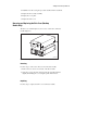
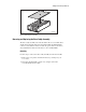
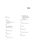
SHR-1204
Figure 4. Drive Caddy Assembly Parts
3. Disconnect the drive power “Y” cable (2) from the power supply
connector.
4. Disconnect the drive 1 RS-422 cable (3) at the controller PWB end.
5. Remove two M4 x 8mm flat-head screws (4) along the upper edge of
the drive caddy assembly.
6. Remove two M4 extension screws (5) at the top of the drive caddy
assembly.
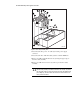
CAUTION: If you’re not careful, you might break the door levers when you lift
the drive caddy assembly out of the base module in the next step. To prevent
this, steady the caddy so it cannot rock forward as it clears the platform when
you’re lifting it up, and do not allow the door levers to touch the strut across
the top of the base module.