
Compaq StorageWorks TL881/TL891 Family MiniLibrary System Reference Guide (July 2000)
Operation 2-3
Compaq Confidential – Need to Know Required
Writer:
Bob Young
Project:
Compaq StorageWorks TL881/TL891 Family MiniLibrary System Reference Guide
Comments:
Part Number:
127510-002
File Name:
c-ch2 Operation.doc
Last Saved On:
7/12/00 10:51 AM
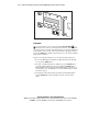
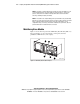
Power Switch
The power switch controls the supply of AC power to the unit. The switch is
recessed into the front panel to prevent accidental power-up or power-down.
Press 1 to turn the unit on and press 0 to turn the unit off.
NOTE:
The Expansion Unit must be turned on after or simultaneously with the other
modules. If this is not done, the Expansion Unit can not be notified of the presence of one
or more of the other modules.
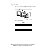
Control Panels
The Expansion Unit control panel (Figure 2-2) contains three LED indicators,
a four-line by 20–character backlit LCD display, and four pushbuttons. The
pushbuttons let you navigate through the menu structure to select and display
operating modes, device status, diagnostic and maintenance functions, device
history and error statistics, and system configuration.
LED Indicators
The three LED indicators on the control panel are labeled Ready (green), Alert
(yellow), and Fault (red).
■
Ready (green) - lights when the system is ready to accept commands,
either from the control panel or from the host computer. The Ready
indicator goes out when you enter the Menu Mode.
■
Alert (yellow) - indicates that a fault or some other matter that requires
attention has occurred in one of the modules in the system. Line 2 of the
display blinks the number of the module where the fault has occurred.
The control panel of the indicated module might give a further
indication of the cause of the alert. Often, when the Alert LED is lit, a
Fault LED is lighted on one or more of the MiniLibrary Base Modules
as well.
■
Fault (red) - indicates that a fault has occurred in the Expansion Unit, or
that the magazine door is unable to close. When the Fault LED lights, a
Fault screen appears on the LCD display. The Fault screen is described
later in this chapter. A list of Fault Symptom Codes (FSC) and Error
Recovery Procedures (ERP) shown in Chapter 6, “Diagnostics and
Troubleshooting.”