
DDR3 memory technology


10
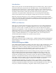
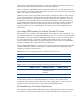
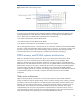
Figure 4: DDR3 DIMM with temperature sensor.
As a starting point, HP engineers have performed extensive modeling and testing to determine the
operating temperature of each DRAM on a DIMM based on the readings from the DDR3 DIMM
sensor. These values are determined by evaluating each of the following.
• The measured temperature from the DIMM sensor
• The relative location of each DRAM on the DIMM
• The direction of the airflow across the DIMM in a given server system
The iLO management processor in each ProLiant server collects this information from the DDR3 DIMMs
and uses it, along with temperature data from other sensors in the server, to control fan cooling inside
the server. This Sea of Sensors fan control technology ensures optimal cooling and helps prevent
possible system failure while reducing power consumption by eliminating overcooling.
DDR3 memory and NUMA systems architectures
DDR3 is a stand-alone memory specification. But its use in servers goes hand-in-hand with the
transition to new server architectures that use Non-Uniform Memory Access (NUMA). AMD
Opteron™–based servers have used NUMA architecture since their inception, with DDR1and later
DDR2 memory. The AMD-based ProLiant G7 servers use an updated NUMA architecture that supports
DDR3 memory. Starting in G6 and G7, Intel-based HP ProLiant servers began incorporating NUMA
architecture along with other new features. The NUMA server architectures and DDR3 address
memory throughput and latency issues that were limiting system performance under older architectures
as system memory footprints continued to increase. All ProLiant Gen8 servers utilize NUMA
architecture.
Older server architectures
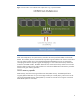
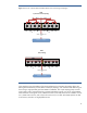
Figure 5 shows the typical architecture for a two-processor (2P) server that used the traditional
memory architecture. With this general design, known as uniform memory access, memory controllers
and memory channels were located on a centralized system chipset. Each processor used the same
pathway to access all of the system memory, communicating with the memory controllers across the
front side bus. The controllers then accessed the DIMMs on the memory channels, returning the
requested data to the processors. The architecture supported memory controller functions, each of
which managed two memory channels for four memory channels per system. The system supported
larger memory footprints by supporting up to four DDR2 FBDIMMs per channel.