
Hardware reference guide
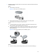
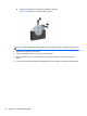
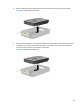
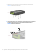
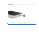
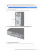
Table Of Contents
- Product Features
- Microtower (MT) Hardware Upgrades
- Serviceability Features
- Warnings and Cautions
- Removing the Computer Access Panel
- Replacing the Computer Access Panel
- Removing the Front Bezel
- Removing Bezel Blanks
- Replacing the Front Bezel
- System Board Connections
- Installing Additional Memory
- Removing or Installing an Expansion Card
- Drive Positions
- Installing and Removing Drives
- Installing a Security Lock
- Small Form Factor (SFF) Hardware Upgrades
- Serviceability Features
- Warnings and Cautions
- Removing the Computer Access Panel
- Replacing the Computer Access Panel
- Removing the Front Bezel
- Removing Bezel Blanks
- Replacing the Front Bezel
- Changing from Desktop to Tower Configuration
- System Board Connections
- Installing Additional Memory
- Removing or Installing an Expansion Card
- Drive Positions
- Installing and Removing Drives
- Installing a Security Lock
- Battery Replacement
- Removing and Replacing a Removable 3.5-inch SATA Hard Drive
- Unlocking the Smart Cover Lock
- Electrostatic Discharge
- Computer Operating Guidelines, Routine Care and Shipping Preparation
- Index

4. Disconnect the power cord from the power outlet and disconnect any external devices.
CAUTION: Regardless of the power-on state, voltage is always present on the system board
as long as the system is plugged into an active AC outlet. You must disconnect the power cord
to avoid damage to the internal components of the computer.
5. Use the Smart Cover FailSafe Key to remove the two tamper-proof screws that secure the Smart
Cover Lock to the chassis.
Figure C-1 Removing the Smart Cover Lock Screws from the Microtower
Figure C-2 Removing the Smart Cover Lock Screws from the Small Form Factor
You can now remove the access panel.
To reattach the Smart Cover Lock, secure the lock in place with the tamper-proof screws.
Using the Smart Cover FailSafe Key to Remove the Smart Cover Lock 91