
Hardware reference guide
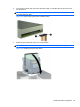
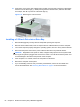
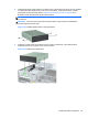
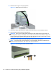
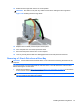
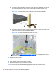
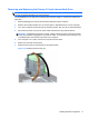
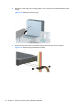
Table Of Contents
- Product Features
- Microtower (MT) Hardware Upgrades
- Serviceability Features
- Warnings and Cautions
- Removing the Computer Access Panel
- Replacing the Computer Access Panel
- Removing the Front Bezel
- Removing Bezel Blanks
- Replacing the Front Bezel
- System Board Connections
- Installing Additional Memory
- Removing or Installing an Expansion Card
- Drive Positions
- Installing and Removing Drives
- Installing a Security Lock
- Small Form Factor (SFF) Hardware Upgrades
- Serviceability Features
- Warnings and Cautions
- Removing the Computer Access Panel
- Replacing the Computer Access Panel
- Removing the Front Bezel
- Removing Bezel Blanks
- Replacing the Front Bezel
- Changing from Desktop to Tower Configuration
- System Board Connections
- Installing Additional Memory
- Removing or Installing an Expansion Card
- Drive Positions
- Installing and Removing Drives
- Installing a Security Lock
- Battery Replacement
- Removing and Replacing a Removable 3.5-inch SATA Hard Drive
- Unlocking the Smart Cover Lock
- Electrostatic Discharge
- Computer Operating Guidelines, Routine Care and Shipping Preparation
- Index
8. Install four M3 metric guide screws in the lower holes on each side of the drive. HP has provided
four extra M3 metric guide screws on the front of the chassis, under the front bezel. The M3
metric guide screws are black. Refer to
Installing and Removing Drives on page 60 for an
illustration of the extra M3 metric guide screws location.
NOTE: When replacing the drive, transfer the four M3 metric guide screws from the old drive to
the new one.
CAUTION: Use only 5-mm long screws as guide screws. Longer screws can damage the
internal components of the drive.
Figure 3-22 Installing Guide Screws in the Optical Drive
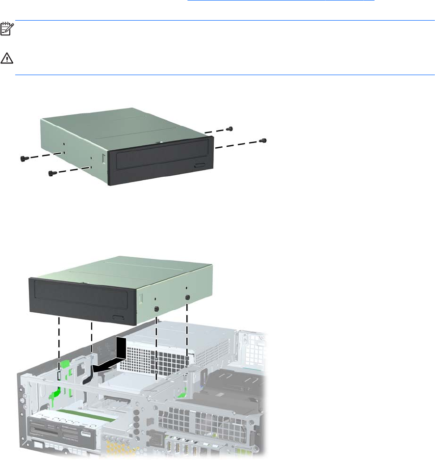
9. Position the guide screws on the drive into the J-slots in the drive bay. Then slide the drive
toward the front of the computer until it locks into place.
Figure 3-23 Installing the Optical Drive
Installing and Removing Drives 65