
Hardware reference guide
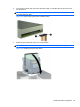
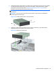
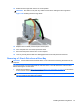
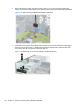
Table Of Contents
- Product Features
- Microtower (MT) Hardware Upgrades
- Serviceability Features
- Warnings and Cautions
- Removing the Computer Access Panel
- Replacing the Computer Access Panel
- Removing the Front Bezel
- Removing Bezel Blanks
- Replacing the Front Bezel
- System Board Connections
- Installing Additional Memory
- Removing or Installing an Expansion Card
- Drive Positions
- Installing and Removing Drives
- Installing a Security Lock
- Small Form Factor (SFF) Hardware Upgrades
- Serviceability Features
- Warnings and Cautions
- Removing the Computer Access Panel
- Replacing the Computer Access Panel
- Removing the Front Bezel
- Removing Bezel Blanks
- Replacing the Front Bezel
- Changing from Desktop to Tower Configuration
- System Board Connections
- Installing Additional Memory
- Removing or Installing an Expansion Card
- Drive Positions
- Installing and Removing Drives
- Installing a Security Lock
- Battery Replacement
- Removing and Replacing a Removable 3.5-inch SATA Hard Drive
- Unlocking the Smart Cover Lock
- Electrostatic Discharge
- Computer Operating Guidelines, Routine Care and Shipping Preparation
- Index
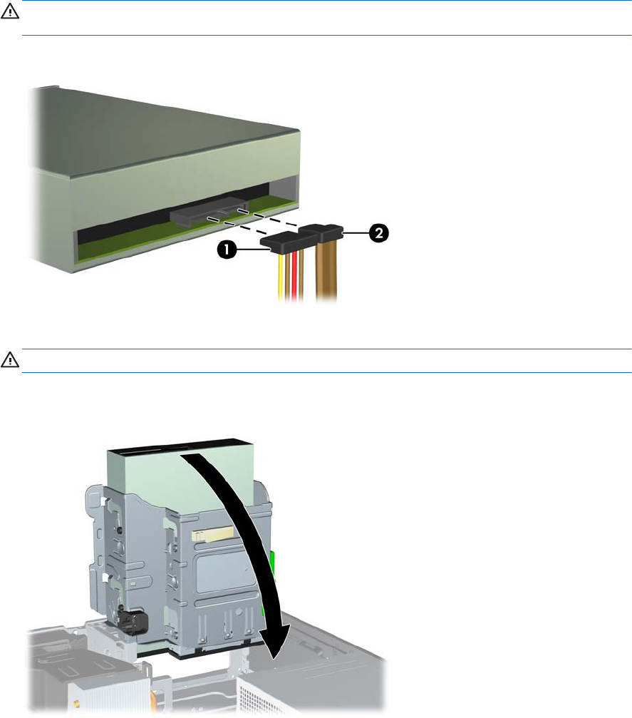
8. If removing an optical drive, disconnect the power cable (1) and data cable (2) from the rear of
the optical drive.
CAUTION: When removing the cables, pull the tab or connector instead of the cable itself to
avoid damaging the cable.
Figure 3-19 Disconnecting the Power and Data Cables
9. Rotate the drive cage back down to its normal position.
CAUTION: Be careful not to pinch any cables or wires when rotating the drive cage down.
Figure 3-20 Rotating the Drive Cage Down
Installing and Removing Drives 63