
Hardware reference guide
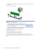
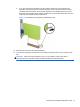

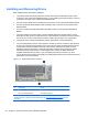
Table Of Contents
- Product Features
- Microtower (MT) Hardware Upgrades
- Serviceability Features
- Warnings and Cautions
- Removing the Computer Access Panel
- Replacing the Computer Access Panel
- Removing the Front Bezel
- Removing Bezel Blanks
- Replacing the Front Bezel
- System Board Connections
- Installing Additional Memory
- Removing or Installing an Expansion Card
- Drive Positions
- Installing and Removing Drives
- Installing a Security Lock
- Small Form Factor (SFF) Hardware Upgrades
- Serviceability Features
- Warnings and Cautions
- Removing the Computer Access Panel
- Replacing the Computer Access Panel
- Removing the Front Bezel
- Removing Bezel Blanks
- Replacing the Front Bezel
- Changing from Desktop to Tower Configuration
- System Board Connections
- Installing Additional Memory
- Removing or Installing an Expansion Card
- Drive Positions
- Installing and Removing Drives
- Installing a Security Lock
- Battery Replacement
- Removing and Replacing a Removable 3.5-inch SATA Hard Drive
- Unlocking the Smart Cover Lock
- Electrostatic Discharge
- Computer Operating Guidelines, Routine Care and Shipping Preparation
- Index
18. Lock any security devices that were disengaged when the access panel was removed.
19. Reconfigure the computer, if necessary.
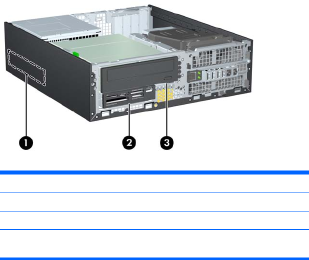
Drive Positions
Figure 3-16 Drive Positions
Table 3-2 Drive Positions
1 3.5-inch internal hard drive bay
2 3.5-inch drive bay for optional drives (media card reader shown)
3 5.25-inch drive bay for optional drives (optical drive shown)
NOTE: The drive configuration on your computer may be different than the drive
configuration shown above.
To verify the type and size of the storage devices installed in the computer, run Computer Setup.
Drive Positions 59