
Hardware reference guide
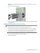
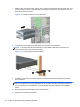
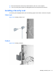
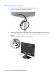
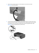
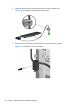
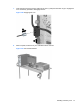
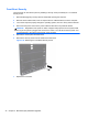
Table Of Contents
- Product Features
- Microtower (MT) Hardware Upgrades
- Serviceability Features
- Warnings and Cautions
- Removing the Computer Access Panel
- Replacing the Computer Access Panel
- Removing the Front Bezel
- Removing Bezel Blanks
- Replacing the Front Bezel
- System Board Connections
- Installing Additional Memory
- Removing or Installing an Expansion Card
- Drive Positions
- Installing and Removing Drives
- Installing a Security Lock
- Small Form Factor (SFF) Hardware Upgrades
- Serviceability Features
- Warnings and Cautions
- Removing the Computer Access Panel
- Replacing the Computer Access Panel
- Removing the Front Bezel
- Removing Bezel Blanks
- Replacing the Front Bezel
- Changing from Desktop to Tower Configuration
- System Board Connections
- Installing Additional Memory
- Removing or Installing an Expansion Card
- Drive Positions
- Installing and Removing Drives
- Installing a Security Lock
- Battery Replacement
- Removing and Replacing a Removable 3.5-inch SATA Hard Drive
- Unlocking the Smart Cover Lock
- Electrostatic Discharge
- Computer Operating Guidelines, Routine Care and Shipping Preparation
- Index
3. Slide the security cable through the hole in the Cable lock on the rear of the monitor.
Figure 2-36 Securing the Monitor
4. Use the bracket provided in the kit to secure other peripheral devices by laying the device cable
across the center of the bracket (1) and inserting the security cable through one of the two holes
in the bracket (2). Use the hole in the bracket that best secures the peripheral device cable.
Figure 2-37 Securing Peripheral Devices (Printer Shown)
Installing a Security Lock 39