
Hardware reference guide
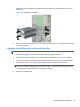
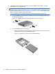
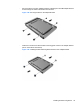
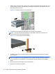
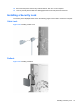
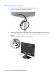
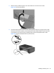
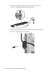
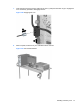
Table Of Contents
- Product Features
- Microtower (MT) Hardware Upgrades
- Serviceability Features
- Warnings and Cautions
- Removing the Computer Access Panel
- Replacing the Computer Access Panel
- Removing the Front Bezel
- Removing Bezel Blanks
- Replacing the Front Bezel
- System Board Connections
- Installing Additional Memory
- Removing or Installing an Expansion Card
- Drive Positions
- Installing and Removing Drives
- Installing a Security Lock
- Small Form Factor (SFF) Hardware Upgrades
- Serviceability Features
- Warnings and Cautions
- Removing the Computer Access Panel
- Replacing the Computer Access Panel
- Removing the Front Bezel
- Removing Bezel Blanks
- Replacing the Front Bezel
- Changing from Desktop to Tower Configuration
- System Board Connections
- Installing Additional Memory
- Removing or Installing an Expansion Card
- Drive Positions
- Installing and Removing Drives
- Installing a Security Lock
- Battery Replacement
- Removing and Replacing a Removable 3.5-inch SATA Hard Drive
- Unlocking the Smart Cover Lock
- Electrostatic Discharge
- Computer Operating Guidelines, Routine Care and Shipping Preparation
- Index
6. Install guide screws on the sides of the drive. If you are installing a 2.5-inch drive, you must
install the drive in an adapter bracket.
NOTE: The hard drive uses 6-32 isolation mounting guide screws. Four extra guide screws are
installed on the exterior of the hard drive bays. The HP-supplied isolation mounting guide screws
are silver and blue. Refer to
Installing and Removing Drives on page 25 for an illustration of the
extra 6-32 isolation mounting guide screws location.
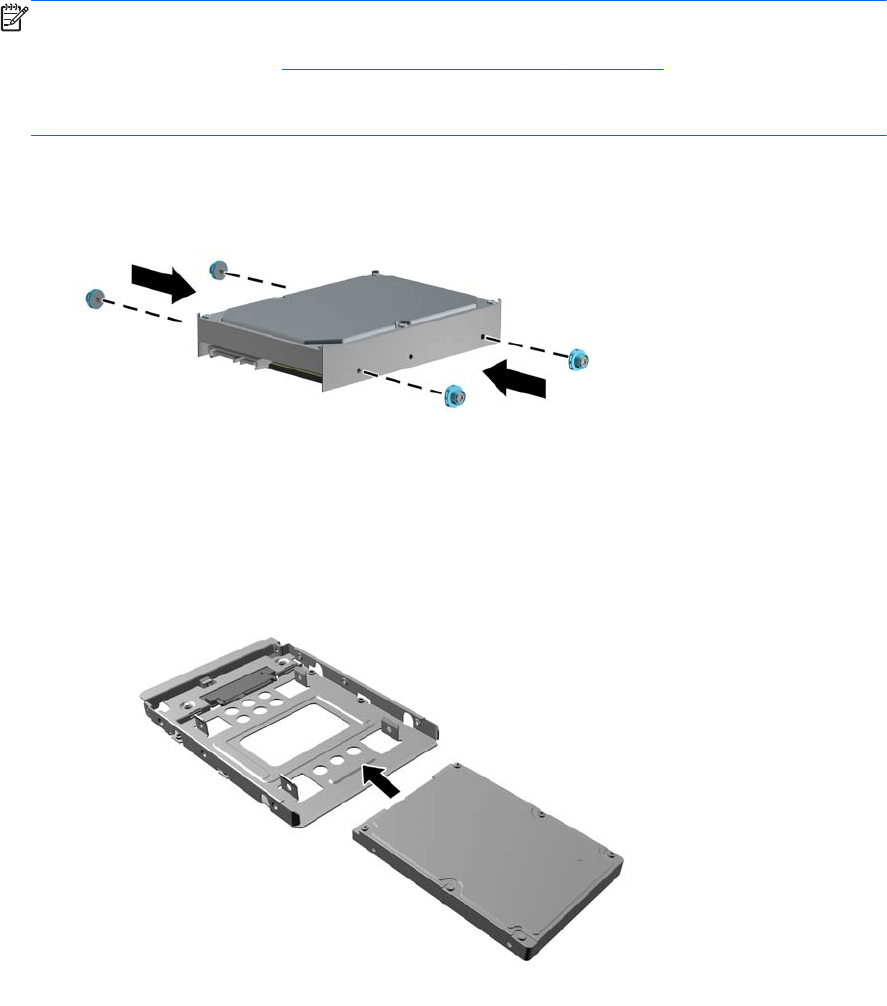
If you are replacing a drive, transfer the guides screws from the old drive to the new one.
●
If you are installing a 3.5-inch hard drive, install four isolation mounting guide screws (two
on each side of the drive).
Figure 2-26 Installing Isolation Mounting Guide Screws in a 3.5-inch Drive
●
If you are installing a 2.5-inch hard drive:
◦
Slide the drive into the bay adapter bracket, ensuring the connector on the drive is fully
inserted into the connector on the adapter bracket.
Figure 2-27 Sliding the 2.5-inch Drive in the Adapter Bracket
34 Chapter 2 Microtower (MT) Hardware Upgrades