
Hardware reference guide
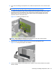
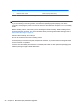
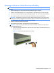
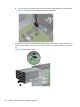
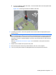
Table Of Contents
- Product Features
- Microtower (MT) Hardware Upgrades
- Serviceability Features
- Warnings and Cautions
- Removing the Computer Access Panel
- Replacing the Computer Access Panel
- Removing the Front Bezel
- Removing Bezel Blanks
- Replacing the Front Bezel
- System Board Connections
- Installing Additional Memory
- Removing or Installing an Expansion Card
- Drive Positions
- Installing and Removing Drives
- Installing a Security Lock
- Small Form Factor (SFF) Hardware Upgrades
- Serviceability Features
- Warnings and Cautions
- Removing the Computer Access Panel
- Replacing the Computer Access Panel
- Removing the Front Bezel
- Removing Bezel Blanks
- Replacing the Front Bezel
- Changing from Desktop to Tower Configuration
- System Board Connections
- Installing Additional Memory
- Removing or Installing an Expansion Card
- Drive Positions
- Installing and Removing Drives
- Installing a Security Lock
- Battery Replacement
- Removing and Replacing a Removable 3.5-inch SATA Hard Drive
- Unlocking the Smart Cover Lock
- Electrostatic Discharge
- Computer Operating Guidelines, Routine Care and Shipping Preparation
- Index
8. Slide the drive into the drive bay, making sure to align the guide screws with the guide slots, until
the drive snaps into place.
Figure 2-21 Sliding the Drives into the Drive Cage
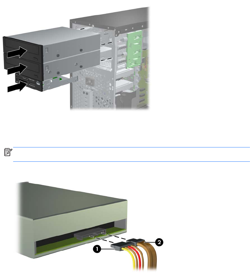
9. Connect the power and data cables to the drive as indicated in the following illustrations.
a. If you are installing an optical drive, connect the power cable (1) and data cable (2) to the
back of the drive.
NOTE: The power cable for the optical drives is a two-headed cable that is routed from
the system board to the rear of the optical drive bays.
Figure 2-22 Connecting the Optical Drive Cables
30 Chapter 2 Microtower (MT) Hardware Upgrades