HP Compaq Business PC Hardware Reference Guide Pro 6300 Series Microtower Pro 6300 Series Small Form Factor
© Copyright 2012 Hewlett-Packard Development Company, L.P. The information contained herein is subject to change without notice. Microsoft, Windows, and Windows Vista are either trademarks or registered trademarks of Microsoft Corporation in the United States and/or other countries. The only warranties for HP products and services are set forth in the express warranty statements accompanying such products and services. Nothing herein should be construed as constituting an additional warranty.
About This Book This guide provides basic information for upgrading HP Compaq Business PCs. WARNING! Text set off in this manner indicates that failure to follow directions could result in bodily harm or loss of life. CAUTION: Text set off in this manner indicates that failure to follow directions could result in damage to equipment or loss of information. NOTE: Text set off in this manner provides important supplemental information.
iv About This Book
Table of contents 1 Product Features ............................................................................................................................................ 1 Standard Configuration Features ......................................................................................................... 1 Microtower (MT) Front Panel Components .......................................................................................... 2 Small Form Factor (SFF) Front Panel Components .............
Front Bezel Security .......................................................................................................... 42 3 Small Form Factor (SFF) Hardware Upgrades ........................................................................................... 44 Serviceability Features ....................................................................................................................... 44 Warnings and Cautions .........................................................................
Appendix D Electrostatic Discharge .............................................................................................................. 92 Preventing Electrostatic Damage ....................................................................................................... 92 Grounding Methods ............................................................................................................................
viii
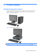
1 Product Features Standard Configuration Features Features may vary depending on the model. For a complete listing of the hardware and software installed in the computer, run the diagnostic utility (included on some computer models only). Figure 1-1 Microtower Configuration Figure 1-2 Small Form Factor Configuration NOTE: The Small Form Factor computer can also be used in a tower orientation. For more information, see Changing from Desktop to Tower Configuration on page 49 in this guide.
Microtower (MT) Front Panel Components Drive configuration may vary by model. Some models have a bezel blank covering one or more drive bays. Table 1-1 Front Panel Components 1 5.25-inch Optical Drives 5 3.5-inch Media Card Reader (optional) 2 Hard Drive Activity Light 6 Dual-State Power Button 3 Microphone/Headphone Connector 7 Power On Light 4 USB (Universal Serial Bus) 2.
Small Form Factor (SFF) Front Panel Components Drive configuration may vary by model. Some models have a bezel blank covering one or more drive bays. Figure 1-3 Front Panel Components Table 1-2 Front Panel Components 1 5.25-inch Optical Drive 5 Microphone/Headphone Connector 2 Dual-State Power Button 6 3.
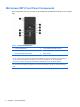
Microtower (MT) Rear Panel Components Figure 1-4 Rear Panel Components Table 1-3 Rear Panel Components 1 Power Cord Connector 6 Line-Out Connector for powered audio devices (green) 2 Line-In Audio Connector (blue) 7 PS/2 Keyboard Connector (purple) 3 PS/2 Mouse Connector (green) 8 VGA Monitor Connector 4 Serial Connector 9 DisplayPort Monitor Connector 5 RJ-45 Network Connector 10 USB 3.0 ports 11 USB 2.
Small Form Factor (SFF) Rear Panel Components Figure 1-5 Rear Panel Components Table 1-4 Rear Panel Components 1 RJ-45 Network Connector 7 DisplayPort Monitor Connector 2 Serial Connector 8 VGA Monitor Connector 3 PS/2 Mouse Connector (green) 9 PS/2 Keyboard Connector (purple) 4 Power Cord Connector 10 Line-Out Connector for powered audio devices (green) 5 USB 2.0 ports 11 Line-In Audio Connector (blue) 6 USB 3.
Media Card Reader Components The media card reader is an optional device available on some models only. Refer to the following illustration and table to identify the media card reader components. Figure 1-6 Media Card Reader Components Table 1-5 Media Card Reader Components No.
Keyboard Figure 1-7 Keyboard Components Table 1-6 Keyboard Components 1 1 Function Keys Perform special functions depending on the software application being used. 2 Editing Keys Includes the following: Insert, Home, Page Up, Delete, End, and Page Down. 3 Status Lights Indicate the status of the computer and keyboard settings (Num Lock, Caps Lock, and Scroll Lock). 4 Numeric Keys Work like a calculator keypad. 5 Arrow Keys Used to navigate through a document or Web site.
Using the Windows Logo Key Use the Windows Logo key in combination with other keys to perform certain functions available in the Windows operating system. Refer to Keyboard on page 7 to identify the Windows Logo key. Table 1-7 Windows Logo Key Functions The following Windows Logo Key functions are available in Microsoft Windows XP, Microsoft Windows Vista, and Microsoft Windows 7.
Table 1-7 Windows Logo Key Functions (continued) Windows Logo Key + right arrow Snaps the window to the right side of the screen Windows Logo Key + down arrow Minimizes the window Windows Logo Key + Shift + up arrow Stretches the window to the top and bottom of the screen Windows Logo Key + Shift + left arrow or right arrow Moves a window from one monitor to another Windows Logo Key + + (on numpad) Zooms in Windows Logo Key + - (on numpad) Zooms out Serial Number Location Each computer has a uni
Figure 1-9 Small Form Factor Serial Number and Product ID Location 10 Chapter 1 Product Features
2 Microtower (MT) Hardware Upgrades Serviceability Features The computer includes features that make it easy to upgrade and service. No tools are needed for most of the installation procedures described in this chapter. Warnings and Cautions Before performing upgrades be sure to carefully read all of the applicable instructions, cautions, and warnings in this guide.
Removing the Computer Access Panel To access internal components, you must remove the access panel: 1. Remove/disengage any security devices that prohibit opening the computer. 2. Remove all removable media, such as compact discs or USB flash drives, from the computer. 3. Turn off the computer properly through the operating system, then turn off any external devices. 4. Disconnect the power cord from the power outlet and disconnect any external devices.
Replacing the Computer Access Panel 1. Slide the lip on the front end of the access panel under the lip on the front of the chassis (1) then press the back end of the access panel onto the unit (2). Figure 2-2 Replacing the Computer Access Panel 2. Ensure that the panel is completely closed (1) and tighten the two thumbscrews that secure the access panel to the chassis (2).
Removing the Front Bezel 1. Remove/disengage any security devices that prohibit opening the computer. 2. Remove all removable media, such as compact discs or USB flash drives, from the computer. 3. Turn off the computer properly through the operating system, then turn off any external devices. 4. Disconnect the power cord from the power outlet and disconnect any external devices.
2. To remove a bezel blank, push the two retaining tabs that hold the bezel blank in place towards the outer right edge of the bezel (1) and slide the bezel blank back and to the right to remove it (2). Figure 2-5 Removing a Bezel Blank Replacing the Front Bezel Insert the three hooks on the left side of the bezel into the rectangular holes on the chassis (1) then rotate the right side of the bezel onto the chassis (2) and snap it into place.
System Board Connections Refer to the following illustrations and tables to identify the system board connectors for your model. Figure 2-7 System Board Connections Table 2-1 System Board Connections 16 No.
Table 2-1 System Board Connections (continued) No. System Board Connector System Board Label Color Component 18 PCI Express x1 X1PCIEXP2 black Expansion Card 19 PCI Express x16 X16PCIEXP black Expansion Card 20 PCI PCI1 white Expansion Card Installing Additional Memory The computer comes with double data rate 3 synchronous dynamic random access memory (DDR3SDRAM) dual inline memory modules (DIMMs).
The system will automatically operate in single channel mode, dual channel mode, or flex mode, depending on how the DIMMs are installed. ● The system will operate in single channel mode if the DIMM sockets are populated in one channel only. ● The system will operate in a higher-performing dual channel mode if the total memory capacity of the DIMMs in Channel A is equal to the total memory capacity of the DIMMs in Channel B. The technology and device width can vary between the channels.
5. Remove the computer access panel. WARNING! To reduce risk of personal injury from hot surfaces, allow the internal system components to cool before touching. 6. Open both latches of the memory module socket (1), and insert the memory module into the socket (2). Figure 2-8 Installing a DIMM NOTE: A memory module can be installed in only one way. Match the notch on the module with the tab on the memory socket. Populate the black DIMM sockets before the white DIMM sockets.
Removing or Installing an Expansion Card The computer has one PCI expansion slot, two PCI Express x1 expansion slots, and one PCI Express x16 expansion slot. NOTE: You can install a PCI Express x1, x4, x8, or x16 expansion card in the PCI Express x16 slot. To remove, replace, or add an expansion card: 1. Remove/disengage any security devices that prohibit opening the computer. 2. Remove all removable media, such as compact discs or USB flash drives, from the computer. 3.
8. Before installing an expansion card, remove the expansion slot cover or the existing expansion card. NOTE: Before removing an installed expansion card, disconnect any cables that may be attached to the expansion card. a. If you are installing an expansion card in a vacant socket, remove the appropriate expansion slot cover on the back of the chassis. Pull the slot cover straight up then away from the inside of the chassis.
b. If you are removing a standard PCI card or PCI Express x1 card, hold the card at each end, and carefully rock it back and forth until the connectors pull free from the socket. Pull the expansion card straight up from the socket then away from the inside of the chassis to release it from the chassis frame. Be sure not to scrape the card against the other components. Figure 2-11 Removing a Standard PCI Expansion Card c.
10. If you are not installing a new expansion card, install an expansion slot cover to close the open slot. CAUTION: After removing an expansion card, you must replace it with a new card or expansion slot cover for proper cooling of internal components during operation. 11.
14. Replace the computer access panel. 15. Reconnect the power cord and turn on the computer. 16. Lock any security devices that were disengaged when the access panel was removed. 17. Reconfigure the computer, if necessary. Drive Positions Figure 2-15 Drive Positions Table 2-2 Drive Positions 1 Two 5.25-inch drive bays for optional drives (optical drives shown) 2 One 3.5-inch drive bay for optional drive (media card reader shown) 3 Secondary 3.
Installing and Removing Drives When installing drives, follow these guidelines: ● The primary Serial ATA (SATA) hard drive must be connected to the dark blue primary SATA connector on the system board labeled SATA0. If you are adding a second hard drive, connect it to the white connector on the system board labeled SATA1. ● Connect the first SATA optical drive to the white SATA connector on the system board labeled SATA2.
No. Guide Screw Device 1 Black M3 Metric Screws All Drives (except hard drives) 2 Silver and Blue 6-32 Isolation Mounting Screws Secondary Hard Drive CAUTION: To prevent loss of work and damage to the computer or drive: If you are inserting or removing a drive, shut down the operating system properly, turn off the computer, and unplug the power cord. Do not remove a drive while the computer is on or in standby mode. Before handling a drive, ensure that you are discharged of static electricity.
Removing a 5.25-inch or 3.5-inch Drive from a Drive Bay CAUTION: All removable media should be taken out of a drive before removing the drive from the computer. 1. Remove/disengage any security devices that prohibit opening the computer. 2. Remove all removable media, such as compact discs or USB flash drives, from the computer. 3. Turn off the computer properly through the operating system, then turn off any external devices. 4.
b. If you are removing a media card reader, disconnect the USB cable from the system board. Figure 2-18 Disconnecting the Media Card Reader USB Cable 7. A latch drive bracket with release tabs secures the drives in the drive bay. Lift the release tab on the latch drive bracket (1) for the drive you want to remove, then slide the drive from its drive bay (2).
Installing a 5.25-inch or 3.5-inch Drive into a Drive Bay 1. Remove/disengage any security devices that prohibit opening the computer. 2. Remove all removable media, such as compact discs or USB flash drives, from the computer. 3. Turn off the computer properly through the operating system, then turn off any external devices. 4. Disconnect the power cord from the power outlet and disconnect any external devices.
8. Slide the drive into the drive bay, making sure to align the guide screws with the guide slots, until the drive snaps into place. Figure 2-21 Sliding the Drives into the Drive Cage 9. Connect the power and data cables to the drive as indicated in the following illustrations. a. If you are installing an optical drive, connect the power cable (1) and data cable (2) to the back of the drive.
b. If your are installing a media card reader, connect the USB cable to the USB system board connector labeled MEDIA. Figure 2-23 Connecting the Media Card Reader USB Cable 10. If installing a new drive, connect the opposite end of the data cable to the appropriate system board connector. NOTE: If you are installing a new SATA optical drive, connect the data cable for the first optical drive to the white SATA connector on the system board labeled SATA2.
Removing a Hard Drive from a Drive Bay NOTE: Before you remove the old hard drive, be sure to back up the data from the old hard drive so that you can transfer the data to the new hard drive. 1. Remove/disengage any security devices that prohibit opening the computer. 2. Remove all removable media, such as compact discs or USB flash drives, from the computer. 3. Turn off the computer properly through the operating system, then turn off any external devices. 4.
7. Release the drive by pulling the release tab away from the drive (1) and sliding the drive out of the bay (2). Figure 2-25 Removing a Hard Drive 8. Remove the four guide screws (two on each side) from the old drive. You will need these screws to install a new drive. Installing a Hard Drive into an Internal Drive Bay NOTE: The system does not support Parallel ATA (PATA) hard drives. 1. Remove/disengage any security devices that prohibit opening the computer. 2.
6. Install guide screws on the sides of the drive. If you are installing a 2.5-inch drive, you must install the drive in an adapter bracket. NOTE: The hard drive uses 6-32 isolation mounting guide screws. Four extra guide screws are installed on the exterior of the hard drive bays. The HP-supplied isolation mounting guide screws are silver and blue. Refer to Installing and Removing Drives on page 25 for an illustration of the extra 6-32 isolation mounting guide screws location.
◦ Secure the drive to the bay adapter bracket by installing four black M3 adapter bracket screws through the sides of the bracket into the drive. Figure 2-28 Securing the Drive in the Adapter Bracket ◦ Install four 6-32 silver and blue isolation mounting guide screws in the adapter bracket (two on each side of the bracket).
7. Slide the drive into the drive bay, making sure to align the guide screws with the guide slots, until the drive snaps into place. The bottom bay is for the primary hard drive. The upper bay is for an optional secondary hard drive. Figure 2-30 Sliding a Hard Drive into the Drive Bay 8. Connect the power cable (1) and data cable (2) to the back of the hard drive. NOTE: The power cable for the hard drives is a two-headed cable that is routed from the system board to the rear of the hard drive bays.
12. Reconnect the power cord and any external devices, then turn on the computer. 13. Lock any security devices that were disengaged when the access panel was removed. Installing a Security Lock The security locks displayed below and on the following pages can be used to secure the computer.
HP Business PC Security Lock 1. Fasten the security cable by looping it around a stationary object. Figure 2-34 Securing the Cable to a Fixed Object 2. Insert the Cable lock into the Cable lock slot on the back of the monitor and secure the lock to the monitor by inserting the key into the key hole on the rear of the lock and rotating the key 90 degrees.
3. Slide the security cable through the hole in the Cable lock on the rear of the monitor. Figure 2-36 Securing the Monitor 4. Use the bracket provided in the kit to secure other peripheral devices by laying the device cable across the center of the bracket (1) and inserting the security cable through one of the two holes in the bracket (2). Use the hole in the bracket that best secures the peripheral device cable.
5. Thread the keyboard and mouse cables through the computer chassis lock. Figure 2-38 Threading the Keyboard and Mouse Cables 6. Screw the lock to the chassis in the thumbscrew hole using the screw provided.
7. Insert the plug end of the security cable into the lock (1) and push the button in (2) to engage the lock. Use the key provided to disengage the lock. Figure 2-40 Engaging the Lock 8. When complete, all devices in your workstation will be secured.
Front Bezel Security The front bezel can be locked in place by installing a security screw provided by HP. To install the security screw: 1. Remove/disengage any security devices that prohibit opening the computer. 2. Remove all removable media, such as compact discs or USB flash drives, from the computer. 3. Turn off the computer properly through the operating system, then turn off any external devices. 4. Disconnect the power cord from the power outlet and disconnect any external devices.
8. Install the screw through the interior of the front of the chassis into the front bezel. The screw hole is located toward the middle of the right edge of the chassis between the hard drive bay and speaker. Figure 2-43 Installing the Front Bezel Security Screw 9. Replace the access panel. 10. Reconnect the power cord and turn on the computer. 11. Lock any security devices that were disengaged when the access panel was removed.
3 Small Form Factor (SFF) Hardware Upgrades Serviceability Features The computer includes features that make it easy to upgrade and service. No tools are needed for most of the installation procedures described in this chapter. Warnings and Cautions Before performing upgrades be sure to carefully read all of the applicable instructions, cautions, and warnings in this guide.
Removing the Computer Access Panel To access internal components, you must remove the access panel: 1. Remove/disengage any security devices that prohibit opening the computer. 2. Remove all removable media, such as compact discs or USB flash drives, from the computer. 3. Turn off the computer properly through the operating system, then turn off any external devices. 4. Disconnect the power cord from the power outlet and disconnect any external devices.
Replacing the Computer Access Panel Slide the lip on the front end of the access panel under the lip on the front of the chassis (1) then press the back end of the access panel onto the unit so that it locks into place (2).
Removing the Front Bezel 1. Remove/disengage any security devices that prohibit opening the computer. 2. Remove all removable media, such as compact discs or USB flash drives, from the computer. 3. Turn off the computer properly through the operating system, then turn off any external devices. 4. Disconnect the power cord from the power outlet and disconnect any external devices.
2. To remove a bezel blank, push the two retaining tabs that hold the bezel blank in place towards the outer right edge of the bezel (1) and slide the bezel blank back and to the right to remove it (2). Figure 3-4 Removing a Bezel Blank Replacing the Front Bezel Insert the three hooks on the bottom side of the bezel into the rectangular holes on the chassis (1) then rotate the top side of the bezel onto the chassis (2) and snap it into place.
Changing from Desktop to Tower Configuration The Small Form Factor computer can be used in a tower orientation with an optional tower stand that can be purchased from HP. 1. Remove/disengage any security devices that prohibit opening the computer. 2. Remove all removable media, such as compact discs or USB flash drives, from the computer. 3. Turn off the computer properly through the operating system, then turn off any external devices. 4.
System Board Connections Refer to the following illustration and table to identify the system board connectors for your model. Figure 3-7 System Board Connections Table 3-1 System Board Connections 50 No.
Table 3-1 System Board Connections (continued) No. System Board Connector System Board Label Color Component 18 PCI Express x1 X4PCIEXP black Expansion Card 19 PCI Express x16 X16PCIEXP black Expansion Card 20 PCI PCI white Expansion Card Installing Additional Memory The computer comes with double data rate 3 synchronous dynamic random access memory (DDR3SDRAM) dual inline memory modules (DIMMs).
The system will automatically operate in single channel mode, dual channel mode, or flex mode, depending on how the DIMMs are installed. ● The system will operate in single channel mode if the DIMM sockets are populated in one channel only. ● The system will operate in a higher-performing dual channel mode if the total memory capacity of the DIMMs in Channel A is equal to the total memory capacity of the DIMMs in Channel B. The technology and device width can vary between the channels.
6. Remove the computer access panel. WARNING! To reduce risk of personal injury from hot surfaces, allow the internal system components to cool before touching. 7. Rotate up the internal drive bay housing to access the memory module sockets on the system board.
8. Open both latches of the memory module socket (1), and insert the memory module into the socket (2). Figure 3-9 Installing a DIMM NOTE: A memory module can be installed in only one way. Match the notch on the module with the tab on the memory socket. Populate the black DIMM sockets before the white DIMM sockets. For maximum performance, populate the sockets so that the memory capacity is spread as equally as possible between Channel A and Channel B.
Removing or Installing an Expansion Card The computer has one PCI expansion slot, two PCI Express x1 expansion slots, and one PCI Express x16 expansion slot. NOTE: The PCI and PCI Express slots support only low profile cards. You can install a PCI Express x1, x4, x8, or x16 expansion card in the PCI Express x16 slot. To remove, replace, or add an expansion card: 1. Remove/disengage any security devices that prohibit opening the computer. 2.
9. Before installing an expansion card, remove the expansion slot cover or the existing expansion card. NOTE: Before removing an installed expansion card, disconnect any cables that may be attached to the expansion card. a. If you are installing an expansion card in a vacant socket, remove the appropriate expansion slot cover on the back of the chassis. Pull the slot cover straight up then away from the inside of the chassis. Figure 3-11 Removing an Expansion Slot Cover b.
c. If you are removing a PCI Express x16 card, pull the retention arm on the back of the expansion socket away from the card and carefully rock the card back and forth until the connectors pull free from the socket. Pull the expansion card straight up from the socket then away from the inside of the chassis to release it from the chassis frame. Be sure not to scrape the card against the other components. Figure 3-13 Removing a PCI Express x16 Expansion Card 10.
12. To install a new expansion card, hold the card just above the expansion socket on the system board then move the card toward the rear of the chassis (1) so that the bracket on the card is aligned with the open slot on the rear of the chassis. Press the card straight down into the expansion socket on the system board (2). Figure 3-14 Installing an Expansion Card NOTE: When installing an expansion card, press firmly on the card so that the whole connector seats properly in the expansion card slot. 13.
18. Lock any security devices that were disengaged when the access panel was removed. 19. Reconfigure the computer, if necessary. Drive Positions Figure 3-16 Drive Positions Table 3-2 Drive Positions 1 3.5-inch internal hard drive bay 2 3.5-inch drive bay for optional drives (media card reader shown) 3 5.25-inch drive bay for optional drives (optical drive shown) NOTE: The drive configuration on your computer may be different than the drive configuration shown above.
Installing and Removing Drives When installing drives, follow these guidelines: ● The primary Serial ATA (SATA) hard drive must be connected to the dark blue primary SATA connector on the system board labeled SATA0. If you are adding a second hard drive, connect it to the white connector on the system board labeled SATA1. ● Connect a SATA optical drive to the white SATA connector on the system board labeled SATA2.
CAUTION: To prevent loss of work and damage to the computer or drive: If you are inserting or removing a drive, shut down the operating system properly, turn off the computer, and unplug the power cord. Do not remove a drive while the computer is on or in standby mode. Before handling a drive, ensure that you are discharged of static electricity. While handling a drive, avoid touching the connector. For more information about preventing electrostatic damage, refer to Electrostatic Discharge on page 92.
Removing a 5.25-inch Drive from a Drive Bay CAUTION: All removable media should be taken out of a drive before removing the drive from the computer. 1. Remove/disengage any security devices that prohibit opening the computer. 2. Remove all removable media, such as compact discs or USB flash drives, from the computer. 3. Turn off the computer properly through the operating system, then turn off any external devices. 4.
8. If removing an optical drive, disconnect the power cable (1) and data cable (2) from the rear of the optical drive. CAUTION: When removing the cables, pull the tab or connector instead of the cable itself to avoid damaging the cable. Figure 3-19 Disconnecting the Power and Data Cables 9. Rotate the drive cage back down to its normal position. CAUTION: Be careful not to pinch any cables or wires when rotating the drive cage down.
10. Press down on the green drive retainer button located on the left side of the drive to disengage the drive from the drive cage (1). While pressing the drive retainer button, slide the drive back until it stops, then lift it up and out of the drive cage (2). Figure 3-21 Removing the 5.25-inch Drive Installing a 5.25-inch Drive into a Drive Bay 1. Remove/disengage any security devices that prohibit opening the computer. 2.
8. Install four M3 metric guide screws in the lower holes on each side of the drive. HP has provided four extra M3 metric guide screws on the front of the chassis, under the front bezel. The M3 metric guide screws are black. Refer to Installing and Removing Drives on page 60 for an illustration of the extra M3 metric guide screws location. NOTE: When replacing the drive, transfer the four M3 metric guide screws from the old drive to the new one. CAUTION: Use only 5-mm long screws as guide screws.
10. Rotate the drive cage to its upright position. Figure 3-24 Rotating the Drive Cage Up 11. Connect the SATA data cable to the white SATA system board connector labeled SATA2. 12. Route the data cable through the cable guides. CAUTION: There are two cable guides that keep the data cable from being pinched by the drive cage when raising or lowering it. One is located on the bottom side of the drive cage. The other is located on the chassis frame under the drive cage.
14. Rotate the drive cage back down to its normal position. CAUTION: Be careful not to pinch any cables or wires when rotating the drive cage down. Figure 3-26 Rotating the Drive Cage Down 15. Replace the front bezel (if removed) and access panel. 16. If the computer was on a stand, replace the stand. 17. Reconnect the power cord and turn on the computer. 18. Lock any security devices that were disengaged when the access panel was removed. Removing a 3.
2. Disconnect the drive cables from the rear of the drive, or, if you are removing a media card reader, disconnect the USB cable from the system board as indicated in the following illustration. Figure 3-27 Disconnecting the Media Card Reader USB Cable 3. Press down on the green drive retainer button located on the left side of the drive to disengage the drive from the drive cage (1).
Installing a 3.5-inch Drive into a Drive Bay The 3.5-inch bay is located underneath the 5.25-inch drive. To install a drive into the 3.5-inch bay: NOTE: Install guide screws to ensure the drive will line up correctly in the drive cage and lock in place. HP has provided extra guide screws for the drive bays (four 6-32 standard screws and four M3 metric screws), installed in the front of the chassis, under the front bezel. A secondary hard drive uses 6-32 standard screws.
5. Connect the appropriate drive cables: a. If installing a second hard drive, connect the power cable (1) and data cable (2) to the rear of the drive and connect the other end of the data cable to the white connector on the system board labeled SATA1. Figure 3-31 Connecting the Secondary Hard Drive Power Cable and Data Cable b. If installing a media card reader, connect the USB cable from the media card reader to the USB connector on the system board labeled MEDIA.
Removing and Replacing the Primary 3.5-inch Internal Hard Drive NOTE: Before you remove the old hard drive, be sure to back up the data from the old hard drive so that you can transfer the data to the new hard drive. The preinstalled 3.5-inch hard drive is located under the power supply. To remove and replace the hard drive: 1. Remove/disengage any security devices that prohibit opening the computer. 2. Remove all removable media, such as compact discs or USB flash drives, from the computer. 3.
8. Rotate the power supply to its upright position. The hard drive is located beneath the power supply. Figure 3-34 Raising the Power Supply 9. Disconnect the power cable (1) and data cable (2) from the back of the hard drive.
10. Press down on the green release latch next to the hard drive (1). While holding the latch down, slide the drive forward until it stops, then lift the drive up and out of the bay (2). Figure 3-36 Removing the Hard Drive 11. To install a hard drive, you must transfer the silver and blue isolation mounting guide screws from the old hard drive to the new hard drive.
12. Align the guide screws with the slots on the chassis drive cage, press the hard drive down into the bay, then slide it back until it stops and locks in place. Figure 3-38 Installing the Hard Drive 13. Connect the power cable (1) and data cable (2) to the back of the hard drive. NOTE: If the system has only one SATA hard drive, the data cable must be connected to the dark blue connector labeled SATA0 on the system board to avoid any hard drive performance problems.
Installing a Security Lock The security locks displayed below and on the following pages can be used to secure the computer.
HP Business PC Security Lock 1. Fasten the security cable by looping it around a stationary object. Figure 3-42 Securing the Cable to a Fixed Object 2. Insert the Cable lock into the Cable lock slot on the back of the monitor and secure the lock to the monitor by inserting the key into the key hole on the rear of the lock and rotating the key 90 degrees.
3. Slide the security cable through the hole in the Cable lock on the rear of the monitor. Figure 3-44 Securing the Monitor 4. Use the bracket provided in the kit to secure other peripheral devices by laying the device cable across the center of the bracket (1) and inserting the security cable through one of the two holes in the bracket (2). Use the hole in the bracket that best secures the peripheral device cable.
5. Thread the keyboard and mouse cables through the computer chassis lock. Figure 3-46 Threading the Keyboard and Mouse Cables 6. Screw the lock to the chassis in the thumbscrew hole using the screw provided.
7. Insert the plug end of the security cable into the lock (1) and push the button in (2) to engage the lock. Use the key provided to disengage the lock. Figure 3-48 Engaging the Lock 8. When complete, all devices in your workstation will be secured.
Front Bezel Security The front bezel can be locked in place by installing a security screw provided by HP. To install the security screw: 1. Remove/disengage any security devices that prohibit opening the computer. 2. Remove all removable media, such as compact discs or USB flash drives, from the computer. 3. Turn off the computer properly through the operating system, then turn off any external devices. 4. Disconnect the power cord from the power outlet and disconnect any external devices.
9. Install the security screw next to the middle front bezel release tab to secure the front bezel in place. Figure 3-51 Installing the Front Bezel Security Screw 10. Replace the access panel. 11. If the computer was on a stand, replace the stand. 12. Reconnect the power cord and turn on the computer. 13. Lock any security devices that were disengaged when the access panel was removed.
A Battery Replacement The battery that comes with the computer provides power to the real-time clock. When replacing the battery, use a battery equivalent to the battery originally installed in the computer. The computer comes with a 3-volt lithium coin cell battery. WARNING! The computer contains an internal lithium manganese dioxide battery. There is a risk of fire and burns if the battery is not handled properly. To reduce the risk of personal injury: Do not attempt to recharge the battery.
7. Depending on the type of battery holder on the system board, complete the following instructions to replace the battery. Type 1 a. Lift the battery out of its holder. Figure A-1 Removing a Coin Cell Battery (Type 1) b. Slide the replacement battery into position, positive side up. The battery holder automatically secures the battery in the proper position. Type 2 a. To release the battery from its holder, squeeze the metal clamp that extends above one edge of the battery.
b. Insert the new battery and position the clip back into place. Figure A-3 Removing a Coin Cell Battery (Type 3) NOTE: After the battery has been replaced, use the following steps to complete this procedure. 8. Replace the computer access panel. 9. Plug in the computer and turn on power to the computer. 10. Reset the date and time, your passwords, and any special system setups using Computer Setup. 11. Lock any security devices that were disengaged when the computer access panel was removed.
B Removing and Replacing a Removable 3.5-inch SATA Hard Drive Some models are equipped with a Removable SATA Hard Drive Enclosure in the 5.25-inch internal drive bay. The hard drive is housed in a carrier that can be quickly and easily removed from the drive bay. To remove and replace a drive in the carrier: NOTE: Before you remove the old hard drive, be sure to back up the data from the old hard drive so that you can transfer the data to the new hard drive. 1.
3. Remove the adhesive strip that secures the thermal sensor to the top of the hard drive (1) and move the thermal sensor away from the carrier (2). Figure B-2 Removing the Thermal Sensor 4. Remove the four screws from the bottom of the hard drive carrier. Figure B-3 Removing the Security Screws 86 Appendix B Removing and Replacing a Removable 3.
5. Slide the hard drive back to disconnect it from the carrier then lift it up and out of the carrier. Figure B-4 Removing the Hard Drive 6. Place the new hard drive in the carrier then slide the hard drive back so that it seats in the SATA connector on the carrier's circuit board. Be sure the connector on the hard drive is pressed all the way into the connector on the carrier's circuit board.
7. Replace the four screws in the bottom of the carrier to hold the drive securely in place. Figure B-6 Replacing the Security Screws 8. Place the thermal sensor on top of the hard drive in a position that does not cover the label (1) and attach the thermal sensor to the top of the hard drive with the adhesive strip (2). Figure B-7 Replacing the Thermal Sensor 88 Appendix B Removing and Replacing a Removable 3.
9. Slide the cover on the carrier (1) and replace the screw on the rear of the carrier to secure the cover in place (2). Figure B-8 Replacing the Carrier Cover 10. Slide the hard drive carrier into the enclosure on the computer and lock it with the key provided. NOTE: The carrier must be locked for power to be supplied to the hard drive.
C Unlocking the Smart Cover Lock NOTE: The Smart Cover Lock is an optional feature included on some models only. The Smart Cover Lock is a software-controllable cover lock, controlled by the setup password. This lock prevents unauthorized access to the internal components. The computer ships with the Smart Cover Lock in the unlocked position. For more information about locking the Smart Cover Lock, refer to the Desktop Management Guide.
4. Disconnect the power cord from the power outlet and disconnect any external devices. CAUTION: Regardless of the power-on state, voltage is always present on the system board as long as the system is plugged into an active AC outlet. You must disconnect the power cord to avoid damage to the internal components of the computer. 5. Use the Smart Cover FailSafe Key to remove the two tamper-proof screws that secure the Smart Cover Lock to the chassis.
D Electrostatic Discharge A discharge of static electricity from a finger or other conductor may damage system boards or other static-sensitive devices. This type of damage may reduce the life expectancy of the device. Preventing Electrostatic Damage To prevent electrostatic damage, observe the following precautions: ● Avoid hand contact by transporting and storing products in static-safe containers. ● Keep electrostatic-sensitive parts in their containers until they arrive at static-free workstations.
E Computer Operating Guidelines, Routine Care and Shipping Preparation Computer Operating Guidelines and Routine Care Follow these guidelines to properly set up and care for the computer and monitor: ● Keep the computer away from excessive moisture, direct sunlight, and extremes of heat and cold. ● Operate the computer on a sturdy, level surface. Leave a 10.2-cm (4-inch) clearance on all vented sides of the computer and above the monitor to permit the required airflow.
Optical Drive Precautions Be sure to observe the following guidelines while operating or cleaning the optical drive. Operation ● Do not move the drive during operation. This may cause it to malfunction during reading. ● Avoid exposing the drive to sudden changes in temperature, as condensation may form inside the unit. If the temperature suddenly changes while the drive is on, wait at least one hour before you turn off the power. If you operate the unit immediately, it may malfunction while reading.
Index A access panel locking and unlocking 90 MT removal 12 MT replacement 13 SFF removal 45 SFF replacement 46 SFF replacement 48 SFF security 80 front panel components MT 2 SFF 3 G guide screws MT location 25 SFF location 60 B battery replacement 82 C computer operating guidelines 93 D DIMMs.
MT front bezel 14 MT hard drive 32 MT media card reader 27 MT optical drive 27 SFF bezel blanks 47 SFF computer access panel 45 SFF expansion card 55 SFF expansion slot cover 56 SFF front bezel 47 SFF hard drive 71 SFF media card reader 67 SFF optical drive 62 Smart Cover Lock 90 S security MT front bezel 42 MT HP Business PC Security Lock 38 MT padlock 37 SFF cable lock 37, 75 SFF front bezel 80 SFF HP Business PC Security Lock 76 SFF padlock 75 Smart Cover Lock 90 serial number locations 9 shipping prepar