HP Compaq LE1852ms LED Backlit LCD Monitor User Guide
© 2012 Hewlett-Packard Development Company, L.P. Microsoft, Windows, and Windows Vista are either trademarks or registered trademarks of Microsoft Corporation in the United States and/or other countries. The only warranties for HP products and services are set forth in the express warranty statements accompanying such products and services. Nothing herein should be construed as constituting an additional warranty. HP shall not be liable for technical or editorial errors or omissions contained herein.
About This Guide This guide provides information on monitor features, setting up the monitor, and technical specifications. WARNING! Text set off in this manner indicates that failure to follow directions could result in bodily harm or loss of life. CAUTION: Text set off in this manner indicates that failure to follow directions could result in damage to equipment or loss of information. NOTE: Text set off in this manner provides important supplemental information.
iv About This Guide
Table of contents 1 Product Features ............................................................................................................................................ 1 HP LCD Monitor ................................................................................................................................... 1 2 Setting Up the Monitor ...................................................................................................................................
vi
1 Product Features HP LCD Monitor The LCD (liquid crystal display) monitor has an active matrix, thin-film transistor (TFT) panel. The monitor features include: ● LE1852ms model, 47.0 cm (18.
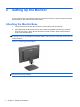
2 Setting Up the Monitor To set up the monitor, ensure that the power is turned off to the monitor, computer system, and other attached devices, then follow the instructions below. Attaching the Monitor Base 1. Lift the base from the monitor box and set it on a flat surface such as a table top. 2. Using both hands, lift the monitor from its box, position the pedestal over the base, and press down firmly to lock it in place.
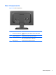
Rear Components Figure 2-2 Rear Components Component Function 1 AC Power Out Connector Connects the AC power cable to the Thin Client power adapter. 2 AC Power Connector Connects the AC power cord to the monitor. 3 DC Connector Connects the DC to DC cable to the monitor and to the HP t150 or HP t200 Zero Client for MultiSeat. 4 VGA Connector Connects the VGA cable to the monitor.
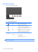
Front Panel Controls Figure 2-3 Monitor Front Panel Controls Table 2-1 Monitor Front Panel Controls Control Function 1 Menu Opens, selects or exits the OSD menu. 2 Minus If the OSD menu is on, press to navigate backward through the OSD menu and decrease adjustment levels. 3 Plus If the OSD menu is on, press to navigate forward through the OSD menu and increase adjustment levels. 4 OK/auto If the OSD menu is on, press to select the highlighted menu item.
Adjusting the Monitor Tilt the monitor's panel forward or backward to set it to a comfortable eye level. Figure 2-4 Tilting the Monitor Removing the Monitor Pedestal Base You can remove the monitor panel from the pedestal base to install the panel on a wall, a swing arm, or other mounting fixture. CAUTION: Before beginning to disassemble the monitor, be sure the monitor is turned off and the power and signal cables are both disconnected. 1.
3. Remove the four pedestal neck screws (1) and lift the pedestal neck (2) off of the monitor panel. Figure 2-5 Removing the Pedestal Neck Screws Mounting the Monitor The monitor panel can be attached to a wall, swing arm, or other mounting fixture. NOTE: 1. This apparatus is intended to be supported by UL or CSA Listed wall mount bracket. Remove the monitor panel from the pedestal base. Refer to Removing the Monitor Pedestal Base on page 5.
2. To attach the monitor to a swing arm, insert four 10mm screws through the holes on the swing arm plate and into the mounting holes on the monitor. Figure 2-6 Mounting the Monitor To attach the monitor to other mounting fixtures, follow the instructions included with the mounting fixture to ensure that the monitor is safely attached. 3. Reconnect the cables to the monitor panel.
2. Slide the HP t150 or HP t200 Zero Client for MultiSeat onto the bracket. Figure 2-8 Installing the MultiSeat Solution 3. Connect the short VGA signal cable from the VGA connector on the MultiSeat Solution to the VGA connector on the monitor.
4. Connect the DC power cable to the DC OUT connector on the monitor (1) and into the power connector on the HP t150 or HP t200 Zero Client for MultiSeat (2), and then plug one end of the power cord into the AC power connector on the back of the monitor (3), and the other end into an electrical wall outlet (4). Figure 2-10 Connecting the DC Power Cable and the Power Cord WARNING! To reduce the risk of electric shock or damage to the equipment: Do not disable the power cord grounding plug.
2. Attach the mounting bracket to the Thin Client using the 4 screws to mount the bracket to the VESA mounting holes on the Thin Client. Figure 2-11 Mounting Quick Release and Quick Release Bracket to the Monitor and the Thin Client 3. Mount the Thin Client onto the Quick Release on the monitor. Figure 2-12 Mounting the Thin Client onto the Quick Release 10 4. Plug one end of the short power cable (provided) into the power adapter (1) and the other end into the AC power connector on the monitor (2).
7. Plug one end of the monitor power cord into the monitor (6) and the other end into an electrical wall outlet (7). Figure 2-13 Connecting the Cables to the Monitor and Thin Client WARNING! To reduce the risk of electric shock or damage to the equipment: Do not disable the power cord grounding plug. The grounding plug is an important safety feature. Plug the power cord into a grounded (earthed) electrical outlet that is easily accessible at all times.
8. Secure the Thin Client power adapter by placing the adapter into in the recessed slot in the monitor stand and pushing the adapter bracket down until it engages with the center of the recessed slot. Figure 2-14 Securing the Thin Client Power Adapter Turning on the Monitor 1. Press the power button on the computer to turn it on. 2. Press the power button on the front of the monitor to turn it on.
Installing a Cable Lock You can secure the monitor to a fixed object with an optional cable lock available from HP.
3 Finding More Information Reference Guide Refer to the HP LCD Monitors Reference Guide included on the CD with your monitor for additional information on: ● Optimizing monitor performance ● Safety and maintenance guidelines ● Installing software from the CD ● Using the OSD menu ● Downloading software from the Web ● Agency and regulatory notices ● Troubleshooting and recommended solutions to common problems For additional information on using and adjusting your monitor, go to http://www.hp.
4 Technical Specifications NOTE: All specifications represent the typical specifications provided by HP's component manufacturers; actual performance may vary either higher or lower. Specifications Table 4-1 Specifications Maximum Weight (Unpacked) Dimensions (include base) Height Depth 3.2 kg 7.05 lbs 33.46 cm 13.17 inches 19.18 cm 7.55 inches 44.93 cm 17.
Entering User Modes The video controller signal may occasionally call for a mode that is not preset if: ● You are not using a standard graphics adapter. ● You are not using a preset mode. It this occurs, you may need to readjust the parameters of the monitor screen by using the on-screen display. Your changes can be made to any or all of these modes and saved in memory. The monitor automatically stores the new setting, then recognizes the new mode just as it does a preset mode.