
Specifications
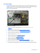
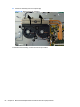
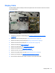
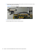


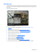
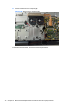
Table Of Contents
- Product Features
- Installing and Customizing the Software
- Computer Setup (F10) Utility
- Serial ATA (SATA) Drive Guidelines and Features
- Identifying the Chassis, Routine Care, and Disassembly Preparation
- Removal and Replacement Procedures All-in One (AIO) Chassis
- Preparing to Disassemble the Computer
- Synchronizing the Optional Wireless Keyboard or Mouse
- Center Access Panel
- Stand
- Memory Access Panel
- Drive Access Panel
- Optical Drive
- Hard Drive
- Memory
- Top Panel
- Webcam Module
- Rear Cover
- System Board Cover
- Sidekey Board
- Converter Board
- Speakers
- WLAN Module
- Heat Sink (Thermal Module)
- Processor
- Fan Assembly
- Display Cable
- System Board
- Stand Bracket
- Hard Drive and Optical Drive Cables and Connectors
- Front Bezel
- Display Panel
- Password Security and Resetting CMOS
- POST Error Messages
- Troubleshooting Without Diagnostics
- Safety and Comfort
- Solving General Problems
- Solving Power Problems
- Solving Diskette Problems
- Solving Hard Drive Problems
- Solving Media Card Reader Problems
- Solving Display Problems
- Solving Audio Problems
- Solving Printer Problems
- Solving Keyboard and Mouse Problems
- Solving Hardware Installation Problems
- Solving Network Problems
- Solving Memory Problems
- Solving Processor Problems
- Solving CD-ROM and DVD Problems
- Solving USB Flash Drive Problems
- Solving Internet Access Problems
- Solving Software Problems
- Contacting Customer Support
- Connector Pin Assignments
- Power Cord Set Requirements
- Specifications
- Index
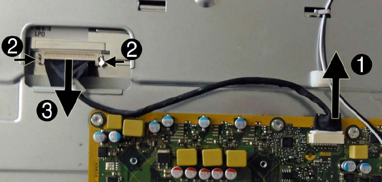
12. Disconnect the cable from the display panel by pressing in the latches on the side of the cable
(2) and pulling it from the connector (3).
Figure 6-48 Removing the display cable
13. Remove the display cable from the computer.
To install the display cable, reverse the removal procedures.
66 Chapter 6 Removal and Replacement Procedures All-in One (AIO) Chassis