
Specifications
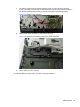
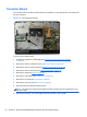
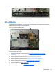
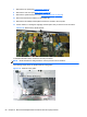
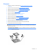
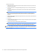
Table Of Contents
- Product Features
- Installing and Customizing the Software
- Computer Setup (F10) Utility
- Serial ATA (SATA) Drive Guidelines and Features
- Identifying the Chassis, Routine Care, and Disassembly Preparation
- Removal and Replacement Procedures All-in One (AIO) Chassis
- Preparing to Disassemble the Computer
- Synchronizing the Optional Wireless Keyboard or Mouse
- Center Access Panel
- Stand
- Memory Access Panel
- Drive Access Panel
- Optical Drive
- Hard Drive
- Memory
- Top Panel
- Webcam Module
- Rear Cover
- System Board Cover
- Sidekey Board
- Converter Board
- Speakers
- WLAN Module
- Heat Sink (Thermal Module)
- Processor
- Fan Assembly
- Display Cable
- System Board
- Stand Bracket
- Hard Drive and Optical Drive Cables and Connectors
- Front Bezel
- Display Panel
- Password Security and Resetting CMOS
- POST Error Messages
- Troubleshooting Without Diagnostics
- Safety and Comfort
- Solving General Problems
- Solving Power Problems
- Solving Diskette Problems
- Solving Hard Drive Problems
- Solving Media Card Reader Problems
- Solving Display Problems
- Solving Audio Problems
- Solving Printer Problems
- Solving Keyboard and Mouse Problems
- Solving Hardware Installation Problems
- Solving Network Problems
- Solving Memory Problems
- Solving Processor Problems
- Solving CD-ROM and DVD Problems
- Solving USB Flash Drive Problems
- Solving Internet Access Problems
- Solving Software Problems
- Contacting Customer Support
- Connector Pin Assignments
- Power Cord Set Requirements
- Specifications
- Index
12. Remove the speakers from the computer (3).
Figure 6-38 Removing the speakers
To install the speakers, reverse the removal procedures.
WLAN Module
The WLAN module is located on the right side of the system board. The module is secured with two
Phillips screws and has two connected antennas.
Figure 6-39 WLAN module location
To remove the WLAN module:
1. Prepare the computer for disassembly (see
Preparing to Disassemble the Computer
on page 29).
2. Remove the center access panel (see
Center Access Panel on page 32).
3. Remove the memory access panel (see
Memory Access Panel on page 34).
4. Remove the drive access panel (see
Drive Access Panel on page 35).
5. Remove the stand (see
Stand on page 33).
6. Remove the optical drive (see
Optical Drive on page 37).
WLAN Module 57