
Specifications
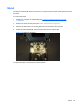
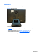
Table Of Contents
- Product Features
- Installing and Customizing the Software
- Computer Setup (F10) Utility
- Serial ATA (SATA) Drive Guidelines and Features
- Identifying the Chassis, Routine Care, and Disassembly Preparation
- Removal and Replacement Procedures All-in One (AIO) Chassis
- Preparing to Disassemble the Computer
- Synchronizing the Optional Wireless Keyboard or Mouse
- Center Access Panel
- Stand
- Memory Access Panel
- Drive Access Panel
- Optical Drive
- Hard Drive
- Memory
- Top Panel
- Webcam Module
- Rear Cover
- System Board Cover
- Sidekey Board
- Converter Board
- Speakers
- WLAN Module
- Heat Sink (Thermal Module)
- Processor
- Fan Assembly
- Display Cable
- System Board
- Stand Bracket
- Hard Drive and Optical Drive Cables and Connectors
- Front Bezel
- Display Panel
- Password Security and Resetting CMOS
- POST Error Messages
- Troubleshooting Without Diagnostics
- Safety and Comfort
- Solving General Problems
- Solving Power Problems
- Solving Diskette Problems
- Solving Hard Drive Problems
- Solving Media Card Reader Problems
- Solving Display Problems
- Solving Audio Problems
- Solving Printer Problems
- Solving Keyboard and Mouse Problems
- Solving Hardware Installation Problems
- Solving Network Problems
- Solving Memory Problems
- Solving Processor Problems
- Solving CD-ROM and DVD Problems
- Solving USB Flash Drive Problems
- Solving Internet Access Problems
- Solving Software Problems
- Contacting Customer Support
- Connector Pin Assignments
- Power Cord Set Requirements
- Specifications
- Index
Memory
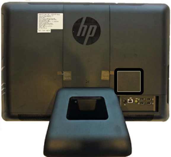
Memory modules are located on the right side of the computer (viewed from behind) under the
memory cover. The computer has two memory slots.
Figure 6-18 Memory module location
The computer comes with double data rate 3 synchronous dynamic random access memory (DDR3-
SDRAM) small outline dual inline memory modules (SODIMMs).
The memory sockets on the system board can be populated with up to two industry-standard
SODIMMs. These memory sockets are populated with at least one preinstalled SODIMM. To achieve
the maximum memory support, you can populate the system board with up to 8 GB of memory.
For proper system operation, the SODIMMs must be:
●
industry-standard 204-pin
●
unbuffered non-ECC PC3-10600 DDR3-1333 MHz-compliant
●
1.5 volt DDR3-SDRAM SODIMMs
The DDR3-SDRAM SODIMMs must also:
●
support CAS latency 9 DDR3 1333 MHz (9-9-9 timing)
●
contain the mandatory Joint Electronic Device Engineering Council (JEDEC) specification
In addition, the computer supports:
●
512-Mbit, 1-Gbit, and 2-Gbit non-ECC memory technologies
●
single-sided and double-sided SODIMMS
●
SODIMMs constructed with x8 and x16 devices; SODIMMs constructed with x4 SDRAM are not
supported
42 Chapter 6 Removal and Replacement Procedures All-in One (AIO) Chassis