
Specifications
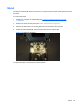
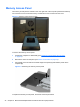
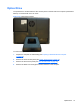
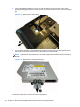
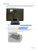
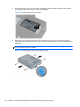
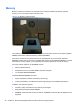
Table Of Contents
- Product Features
- Installing and Customizing the Software
- Computer Setup (F10) Utility
- Serial ATA (SATA) Drive Guidelines and Features
- Identifying the Chassis, Routine Care, and Disassembly Preparation
- Removal and Replacement Procedures All-in One (AIO) Chassis
- Preparing to Disassemble the Computer
- Synchronizing the Optional Wireless Keyboard or Mouse
- Center Access Panel
- Stand
- Memory Access Panel
- Drive Access Panel
- Optical Drive
- Hard Drive
- Memory
- Top Panel
- Webcam Module
- Rear Cover
- System Board Cover
- Sidekey Board
- Converter Board
- Speakers
- WLAN Module
- Heat Sink (Thermal Module)
- Processor
- Fan Assembly
- Display Cable
- System Board
- Stand Bracket
- Hard Drive and Optical Drive Cables and Connectors
- Front Bezel
- Display Panel
- Password Security and Resetting CMOS
- POST Error Messages
- Troubleshooting Without Diagnostics
- Safety and Comfort
- Solving General Problems
- Solving Power Problems
- Solving Diskette Problems
- Solving Hard Drive Problems
- Solving Media Card Reader Problems
- Solving Display Problems
- Solving Audio Problems
- Solving Printer Problems
- Solving Keyboard and Mouse Problems
- Solving Hardware Installation Problems
- Solving Network Problems
- Solving Memory Problems
- Solving Processor Problems
- Solving CD-ROM and DVD Problems
- Solving USB Flash Drive Problems
- Solving Internet Access Problems
- Solving Software Problems
- Contacting Customer Support
- Connector Pin Assignments
- Power Cord Set Requirements
- Specifications
- Index
5. Grasp the handle on top of the hard drive cage (1) and slide the cage toward the outer edge of
the computer, then lift the cage out of the computer (2).
Figure 6-15 Removing the hard drive cage
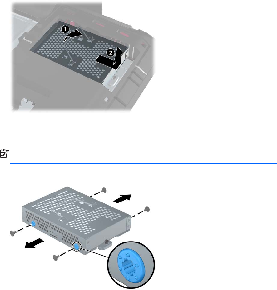
6. Remove the four mounting screws that secure the drive to the cage. Do not remove the blue
rubber grommets behind each screw. They must stay attached to the cage when installing a new
hard drive.
NOTE: Inspect the four blue rubber grommets in case some of them are damaged or lost.
Grommet spare parts are available.
Figure 6-16 Removing the hard drive mounting screws
40 Chapter 6 Removal and Replacement Procedures All-in One (AIO) Chassis