
Specifications
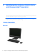
Table Of Contents
- Product Features
- Installing and Customizing the Software
- Computer Setup (F10) Utility
- Serial ATA (SATA) Drive Guidelines and Features
- Identifying the Chassis, Routine Care, and Disassembly Preparation
- Removal and Replacement Procedures All-in One (AIO) Chassis
- Preparing to Disassemble the Computer
- Synchronizing the Optional Wireless Keyboard or Mouse
- Center Access Panel
- Stand
- Memory Access Panel
- Drive Access Panel
- Optical Drive
- Hard Drive
- Memory
- Top Panel
- Webcam Module
- Rear Cover
- System Board Cover
- Sidekey Board
- Converter Board
- Speakers
- WLAN Module
- Heat Sink (Thermal Module)
- Processor
- Fan Assembly
- Display Cable
- System Board
- Stand Bracket
- Hard Drive and Optical Drive Cables and Connectors
- Front Bezel
- Display Panel
- Password Security and Resetting CMOS
- POST Error Messages
- Troubleshooting Without Diagnostics
- Safety and Comfort
- Solving General Problems
- Solving Power Problems
- Solving Diskette Problems
- Solving Hard Drive Problems
- Solving Media Card Reader Problems
- Solving Display Problems
- Solving Audio Problems
- Solving Printer Problems
- Solving Keyboard and Mouse Problems
- Solving Hardware Installation Problems
- Solving Network Problems
- Solving Memory Problems
- Solving Processor Problems
- Solving CD-ROM and DVD Problems
- Solving USB Flash Drive Problems
- Solving Internet Access Problems
- Solving Software Problems
- Contacting Customer Support
- Connector Pin Assignments
- Power Cord Set Requirements
- Specifications
- Index

Table 3-3 Computer Setup—Security (continued)
◦
USB Port 3
◦ USB Port 4
● internal USB Ports
◦ USB Port 1
◦
USB Port 2
◦
USB Port 3
◦
USB Port 10
Slot Security Allows you to disable or enable the PCI Express x1 slot. Default is enable.
Network Boot Enables/disables the computer’s ability to boot from an operating system installed on a network
server. (Feature available on NIC models only; the network controller must be either a PCI
Express expansion card or embedded on the system board.) Default is enable.
System IDs Allows you to update:
●
Asset tag (18-byte identifier).
●
Ownership tag (80-byte identifier displayed during POST).
● Chassis serial number or Universal Unique Identifier (UUID) number. The UUID can only be
updated if the current chassis serial number is invalid. (These ID numbers are normally set in
the factory and are used to uniquely identify the system.)
● Keyboard locale setting (for example, English or German) for System ID entry.
Computer Setup (F10) Utilities 15