
Specifications


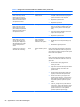
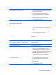
Table Of Contents
- Product Features
- Installing and Customizing the Software
- Computer Setup (F10) Utility
- Serial ATA (SATA) Drive Guidelines and Features
- Identifying the Chassis, Routine Care, and Disassembly Preparation
- Removal and Replacement Procedures All-in One (AIO) Chassis
- Preparing to Disassemble the Computer
- Synchronizing the Optional Wireless Keyboard or Mouse
- Center Access Panel
- Stand
- Memory Access Panel
- Drive Access Panel
- Optical Drive
- Hard Drive
- Memory
- Top Panel
- Webcam Module
- Rear Cover
- System Board Cover
- Sidekey Board
- Converter Board
- Speakers
- WLAN Module
- Heat Sink (Thermal Module)
- Processor
- Fan Assembly
- Display Cable
- System Board
- Stand Bracket
- Hard Drive and Optical Drive Cables and Connectors
- Front Bezel
- Display Panel
- Password Security and Resetting CMOS
- POST Error Messages
- Troubleshooting Without Diagnostics
- Safety and Comfort
- Solving General Problems
- Solving Power Problems
- Solving Diskette Problems
- Solving Hard Drive Problems
- Solving Media Card Reader Problems
- Solving Display Problems
- Solving Audio Problems
- Solving Printer Problems
- Solving Keyboard and Mouse Problems
- Solving Hardware Installation Problems
- Solving Network Problems
- Solving Memory Problems
- Solving Processor Problems
- Solving CD-ROM and DVD Problems
- Solving USB Flash Drive Problems
- Solving Internet Access Problems
- Solving Software Problems
- Contacting Customer Support
- Connector Pin Assignments
- Power Cord Set Requirements
- Specifications
- Index

Interpreting POST Diagnostic Front Panel LEDs and
Audible Codes
This section covers the front panel LED codes as well as the audible codes that may occur before or
during POST that do not necessarily have an error code or text message associated with them.
WARNING! When the computer is plugged into an AC power source, voltage is always applied to
the system board. To reduce the risk of personal injury from electrical shock and/or hot surfaces, be
sure to disconnect the power cord from the wall outlet and allow the internal system components to
cool before touching.
NOTE: If you see flashing LEDs on a PS/2 keyboard, look for flashing LEDs on the front panel of
the computer and refer to the following table to determine the front panel LED codes.
Recommended actions in the following table are listed in the order in which they should be
performed.
Not all diagnostic lights and audible codes are available on all models.
Table B-2 Diagnostic Front Panel LEDs and Audible Codes
Activity Beeps Possible Cause Recommended Action
Green Power LED On. None Computer on. None
Green Power LED flashes
every two seconds.
None Computer in Suspend to
RAM mode (some models
only) or normal Suspend
mode.
None required. Press any key or move the
mouse to wake the computer.
Red Power LED flashes two
times, once every second,
followed by a two second
pause. Beeps stop after fifth
iteration but LEDs continue
until problem is solved.
2 Thermal protection
activated:
Air flow is restricted, a fan
may not be functioning, or
the heatsink is not
properly attached.
1. Clean the air vents on the front, back, or
any other vented side of the computer.
2. Ensure that there is a 10.2 cm (4 in)
clearance on all vented sides of the
computer to permit the required airflow.
3. Ensure that computers are not so near
each other that they are subject to each
other's re-circulated or preheated air.
4. If the computer is within an enclosure,
ensure that there is proper intake and
exhaust ventilation for the enclosure.
5. If a message appears on the screen
indicating that a fan is not working, replace
the fan.
6. Ensure that the heat sink is properly
attached.
Red Power LED flashes three
times, once every second,
followed by a two second
pause. Beeps stop after fifth
iteration but LEDs continue
until problem is solved.
3 Processor not installed
(not an indicator of bad
processor).
1. Check to see that the processor is present.
2. Reseat the processor.
94 Appendix B POST Error Messages