Hardware Reference Guide HP Compaq 8200 Elite All-in-One Business PC
© Copyright 2011 Hewlett-Packard Development Company, L.P. The information contained herein is subject to change without notice. Microsoft, Windows, and Windows Vista are either trademarks or registered trademarks of Microsoft Corporation in the United States and/or other countries. The only warranties for HP products and services are set forth in the express warranty statements accompanying such products and services. Nothing herein should be construed as constituting an additional warranty.
About This Book This guide provides basic information for upgrading this computer model. WARNING! Text set off in this manner indicates that failure to follow directions could result in bodily harm or loss of life. CAUTION: Text set off in this manner indicates that failure to follow directions could result in damage to equipment or loss of information. NOTE: ENWW Text set off in this manner provides important supplemental information.
iv About This Book ENWW
Table of contents 1 Product Features ............................................................................................................................................ 1 Overview .............................................................................................................................................. 1 Front Components ................................................................................................................................ 2 Side Components ..............
vi ENWW
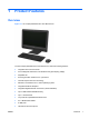
1 Product Features Overview Figure 1-1 HP Compaq 8200 Elite All-in-One Business PC The HP Compaq 8200 Elite All-In One Business PC offers the following features: ENWW ● Integrated All-in-One form factor ● 23-inch diagonal widescreen Full HD WLED anti-glare display (1080p) ● Adjustable tilt ● Second generation Intel® Core™ i processors ● Intel Q67 chipset with vPro technology ● Windows 7 Professional 32- or 64-bit operating system ● Integrated Intel® HD Graphics ● Integrated Gigabit Netwo
● Optional wireless LAN ● Premium stereo speakers ● TPM 1.
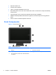
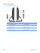
Side Components Figure 1-3 Side Components Table 1-2 Side Components ENWW Component Component 1 HP 6-in-1 Media Card Reader 6 Tray-load optical drive 2 (2) USB 2.
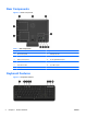
Rear Components Figure 1-4 Rear Components Table 1-3 Rear Components Component Component 1 Drive access panel 7 Security lock slot 2 Center access panel 8 Power connector with LED indicator 3 Memory access panel 9 RJ-45 Gigabit Ethernet port 4 Optical drive location 10 Stereo audio line out 5 Hard drive location 11 (4) USB 2.
Table 1-4 Keyboard Features Component Component 1 Sleep 5 Fast Forward 2 Fast Reverse 6 Mute Volume 3 Play/Pause 7 Decrease Volume 4 Stop 8 Increase Volume Adjusting Tilt Tilt the computer forward up to 5 degrees or backward up to 20 degrees to set it to a comfortable eye level.
2 Hardware Repair and Upgrade Warnings and Cautions Before performing upgrades be sure to carefully read all of the applicable instructions, cautions, and warnings in this guide. WARNING! To reduce the risk of personal injury from electrical shock, hot surfaces, or fire: Disconnect the power cord from the wall outlet and allow the internal system components to cool before touching. Do not plug telecommunications or telephone connectors into the network interface controller (NIC) receptacles.
Connecting Power 1. Plug the power cord into the power connection on the rear of the computer (1). 2. Plug the three-pronged power plug into the power brick (2) and a power outlet (3). Figure 2-1 Connecting Power 3. Plug all peripheral cables into the appropriate ports as needed. 4. Press the power button on the front of the computer to turn it on.
In addition, the computer supports: ● 512-Mbit, 1-Gbit, and 2-Gbit non-ECC memory technologies ● single-sided and double-sided SODIMMS ● SODIMMs constructed with x8 and x16 devices; SODIMMs constructed with x4 SDRAM are not supported NOTE: The system will not operate properly if you install unsupported SODIMMs. There are two memory sockets on the system board located behind the memory access panel. To remove or install memory modules: 1.
7. To remove the memory access panel, pull upward on the two tabs on the inside edge of the panel (1) and slide the panel off the computer (2). Figure 2-3 Removing the Memory Access Panel 8. Pull upward on the two raised tabs on the memory cover and lift the cover off the rear panel.
9. To remove a memory module, press outward on the two latches on each side of the SODIMM (1) then pull the SODIMM out of the socket (2). Figure 2-5 Removing a Memory Module 10. To install a memory module, slide the SODIMM into the socket at approximately a 30° angle (1) then press the SODIMM down (2) so that the latches lock it in place. Figure 2-6 Installing a Memory Module NOTE: A memory module can be installed in only one way. Match the notch on the module with the tab on the memory socket.
11. Press the memory cover back in place. Insert the bottom edge of memory cover into the sheet metal shielding first then press the top edge of memory cover down. Ensure that all the tabs on the memory cover are pressed firmly against the sheet metal shielding. Figure 2-7 Replacing the Memory Cover 12.
13. To replace the center access panel, insert the bottom edge of the panel then press down firmly on each side of the panel working from the bottom to the top so that the panel snaps securely in place. Figure 2-9 Replacing the Center Access Panel 14. Lock any security devices that were disengaged when the center access panel was removed. 15. Reconnect the power cord and external devices then turn on the computer. The computer automatically recognizes the additional memory when you turn on the computer.
6. Remove the center access panel by pulling outward on the panel at the slot on the top edge of the panel. Figure 2-10 Removing the Center Access Panel 7. To remove the drive access panel, push downward on the two tabs on the inside edge of the panel (1) and slide the panel off the computer (2).
8. Loosen the captive screw next to the front of the drive that secures the drive to the computer. You can use either a Torx or slotted screwdriver to loosen the screw. Figure 2-12 Loosening the Hard Drive Security Screw 9. Grasp the handle on top of the hard drive cage (1) and slide the cage toward the outer edge of the computer, then lift the cage out of the computer (2).
10. Remove the four mounting screws that secure the drive to the cage. Do not remove the blue rubber grommets behind each screw. They must stay attached to the cage when installing a new hard drive. Figure 2-14 Removing the Hard Drive Mounting Screws 11. Slide the hard drive out of the cage.
12. Slide the new hard drive into the cage making sure that the connectors on the hard drive are at the opening of the cage. Figure 2-16 Sliding the Hard Drive into the Cage 13. Install the four mounting screws that secure the hard drive to the cage. Make sure that the blue rubber grommets remain attached to the cage behind each screw.
14. Set the hard drive cage down into the bay so that the tabs on the bottom of the cage align with the slots on the chassis and slide the cage toward the center of the computer (1) so that the connector on the rear of the drive is securely seated. Rotate the handle on the cage down (2) and lock it into the clips on top of the cage. Figure 2-18 Installing the Hard Drive Cage 15. Tighten the captive screw to secure the hard drive cage in place.
16. Place the drive access panel on the rear of the computer so that the edge of the panel is slightly hanging off the edge of the computer and slide the panel toward the center of the computer until it snaps in place. Figure 2-20 Replacing the Drive Access Panel 17. To replace the center access panel, insert the bottom edge of the panel then press down firmly on each side of the panel working from the bottom to the top so that the panel snaps securely in place.
the cable to your desk (or other stationary object) and the other to this security slot on the computer. Secure the security lock with the key. Figure 2-22 Installing a Security Lock Synchronizing the Optional Wireless Keyboard or Mouse The optional wireless keyboard and mouse are easy to set up. Just remove the battery tabs on both the keyboard and the mouse. Also, make sure the Power switch on the bottom of the mouse is in the On position (the keyboard does not have a Power switch).
3. Insert the wireless receiver into a USB port on the computer. Figure 2-23 Installing the Wireless Receiver 4. Make sure the Power switch on the bottom of the mouse is in the On position (1). 5. Press the Connect button on the bottom of the mouse (2) for fives seconds. The blue activity LED from the wireless receiver illuminates when the synchronization command has been received and turns off when synchronization is complete. 6.
Removing Batteries from the Wireless Keyboard or Mouse NOTE: The wireless keyboard and mouse are optional components. To remove batteries from the wireless keyboard, remove the battery door on the underside of the keyboard (1) and lift the batteries out of the battery compartment (2). Figure 2-25 Removing Batteries from the Wireless Keyboard To remove batteries from the wireless mouse, remove the battery door on the underside of the mouse (1) and lift the batteries out of the battery compartment (2).
A Electrostatic Discharge A discharge of static electricity from a finger or other conductor may damage system boards or other static-sensitive devices. This type of damage may reduce the life expectancy of the device. Preventing Electrostatic Damage To prevent electrostatic damage, observe the following precautions: ● Avoid hand contact by transporting and storing products in static-safe containers. ● Keep electrostatic-sensitive parts in their containers until they arrive at static-free workstations.
B Computer Operating Guidelines, Routine Care and Shipping Preparation Computer Operating Guidelines and Routine Care Follow these guidelines to properly set up and care for the computer: ENWW ● Keep the computer away from excessive moisture, direct sunlight, and extremes of heat and cold. ● Operate the computer on a sturdy, level surface. Leave a 10.2-cm (4-inch) clearance on all vented sides of the computer to permit the required airflow.
Optical Drive Precautions Be sure to observe the following guidelines while operating or cleaning the optical drive. ● Do not move the drive during operation. This may cause it to malfunction during reading. ● Avoid exposing the drive to sudden changes in temperature, as condensation may form inside the unit. If the temperature suddenly changes while the drive is on, wait at least one hour before you turn off the power. If you operate the unit immediately, it may malfunction while reading.
Index A additional information O optical drive precautions 24 6 C components front 2 rear 4 side 3 computer operating guidelines P power connecting 23 E electrostatic discharge, preventing damage 22 F features keyboard 4 overview 1 front components 2 H hard drive replacing 12 I installation guidelines 6 installing hard drive 12 memory 7 security lock 18 7 R rear components 4 S security lock location 18 shipping preparation 24 side components 3 specifications memory 7 synchronizing wireless keyboard a