Hardware Reference Guide HP Compaq dx2200 Microtower Business PC Document Part Number: 413758-001 January 2006 This guide provides basic information about upgrading this computer model.
© Copyright 2006 Hewlett-Packard Development Company, L.P. The information contained herein is subject to change without notice. Microsoft and Windows are trademarks of Microsoft Corporation in the U.S. and other countries. The only warranties for HP products and services are set forth in the express warranty statements accompanying such products and services. Nothing herein should be construed as constituting an additional warranty.
Contents 1 Hardware Upgrades Serviceability Features . . . . . . . . . . . . . . . . . . . . . . . . . . . . . . . . . . . . . . . . . . . . . . . . . 1–2 Warnings and Cautions . . . . . . . . . . . . . . . . . . . . . . . . . . . . . . . . . . . . . . . . . . . . . . . . . 1–2 Removing the Access Panel and Front Bezel . . . . . . . . . . . . . . . . . . . . . . . . . . . . . . . . 1–3 Removing a 5.25" Drive Bezel Blank . . . . . . . . . . . . . . . . . . . . . . . . . . . . . . . . . . . . . .
Contents 4 Electrostatic Discharge Preventing Electrostatic Damage . . . . . . . . . . . . . . . . . . . . . . . . . . . . . . . . . . . . . . . . . 4–1 Grounding Methods. . . . . . . . . . . . . . . . . . . . . . . . . . . . . . . . . . . . . . . . . . . . . . . . . . . . 4–1 iv www.hp.
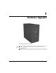
1 Hardware Upgrades HP Compaq dx2200 Microtower drive configuration shown above may be different than your ✎ The computer model. Hardware Reference Guide www.hp.
Hardware Upgrades Serviceability Features The Microtower computer includes features that make it easy to upgrade and service. A Torx T-15 screwdriver is needed for many of the installation procedures described in this chapter. Warnings and Cautions Before performing upgrades be sure to carefully read all of the applicable instructions, cautions, and warnings in this guide.
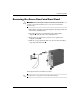
Hardware Upgrades Removing the Access Panel and Front Bezel Ä CAUTION: Before removing the computer access panel, ensure that the computer is turned off and that the power cord is disconnected from the electrical outlet. 1. Turn off the computer properly through the operating system and turn off any external devices. 2. Disconnect the power cord from the power outlet and the computer 1, and disconnect any external devices. 3. Remove the two screws that secure the access panel to the computer chassis 2.
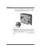
Hardware Upgrades 5. To remove the front bezel, pull outward on all three tabs on the left side of the bezel 1 then rotate the bezel off the chassis 2, beginning with the left side then the right side. Removing the Front Bezel the front bezel, insert the three hooks on the right side of ✎ Tothereplace bezel into the rectangular holes on the chassis then rotate the bezel into place so that the catches on the three tabs on the left side of the bezel snap into place on the chassis. 1-4 www.hp.
Hardware Upgrades Removing a 5.25" Drive Bezel Blank If the computer was not shipped with a drive in the 5.25" option bay, the bay will be covered by a bezel blank. If you add a drive to the option bay, you must first remove the bezel blank. 1. Turn off the computer properly through the operating system and turn off any external devices. 2. Disconnect the power cord from the power outlet and the computer, and disconnect any external devices. 3. Remove the access panel and front bezel.
Hardware Upgrades Removing a 3.5" Drive Bezel Blank If the computer was not shipped with a device in the 3.5" bay, the bay will be covered by a bezel blank. If you install a device in the 3.5" bay, you must first remove the bezel blank. 1. Turn off the computer properly through the operating system and turn off any external devices. 2. Disconnect the power cord from the power outlet and the computer, and disconnect any external devices. 3. Remove the access panel and front bezel.
Hardware Upgrades Installing Additional Memory The computer comes with double data rate 2 synchronous dynamic random access memory (DDR2-SDRAM) dual inline memory modules (DIMMs). DIMMs The memory sockets on the system board can be populated with up to two industry-standard DIMMs. These memory sockets are populated with at least one preinstalled DIMM. The sockets are labeled DIMM1 and DIMM2. To achieve the maximum memory support, you can populate the system board with up to 2GB (2 x 1GB) of memory.
Hardware Upgrades Installing DIMMs Ä CAUTION: The memory module sockets have gold metal contacts. When upgrading the memory, it is important to use memory modules with gold metal contacts to prevent corrosion and/or oxidation resulting from having incompatible metals in contact with each other. Ä CAUTION: Static electricity can damage the electronic components of the computer or optional cards.
Hardware Upgrades 5. Open both latches of the memory module socket 1, and insert the memory module into the socket 2. Installing a DIMM module can be installed in only one way. Match the notch ✎ Aonmemory the module with the tab on the memory socket. 6. Push the module down into the socket, ensuring that the module is fully inserted and properly seated. Make sure the latches are in the closed position 3. 7. Replace the computer access panel and reconnect the power cable.
Hardware Upgrades Installing an Expansion Card The computer has two PCI expansion slots that can accommodate expansion cards up to 17.46 cm (6.875 inches) in length, one PCI Express x1 expansion slot, and one PCI Express x16 expansion slot. 1. Turn off the computer properly through the operating system and turn off any external devices. 2. Disconnect the power cord from the power outlet and the computer, and disconnect any external devices. 3.
Hardware Upgrades 5. If you are installing an expansion card for the first time, you must use a flatblade screwdriver to pry out the metal shield on the rear panel that covers the expansion slot. Be sure to remove the appropriate shield for the expansion card you are installing. Removable Shield Expansion Card Type Top shield PCI Express x16 Second shield PCI Express x1 Third shield PCI Bottom shield PCI 6.
Hardware Upgrades installing an expansion card, press firmly on the card so that ✎ When the whole connector seats properly in the expansion card slot. 7. While holding the expansion card bracket against the chassis, slide the slot cover lock down toward the expansion card bracket to secure it in place and replace the screw that secures the slot cover lock. 8. Connect external cables to the installed card, if needed. Connect internal cables to the system board, if needed. 9.
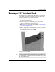
Hardware Upgrades Locating Drive Positions drive configuration shown below may be different than your ✎ The computer model. Drive Positions 1 External 5.25" full-height optical drive bay 2 External 5.25" full-height option drive bay 3 External 3.5" option drive bay (media card reader shown)* 4 Internal 3.5" one-third height bay for optional secondary hard drive 5 Internal 3.5" one-third height bay for primary hard drive *The external 3.
Hardware Upgrades Removing a 5.25" Optical Drive 1. Turn off the computer properly through the operating system and turn off any external devices. 2. Disconnect the power cord from the power outlet and the computer, and disconnect any external devices. 3. Remove the access panel and front bezel. Refer to “Removing the Access Panel and Front Bezel.” 4. Disconnect the power and data cables from the back of the drive. 5.
Hardware Upgrades you are installing a drive in the bottom 5.25" drive bay, remove the ✎ Ifmetal shield that covers the bay by pressing inward on the silver tab on the left side of the chassis then pulling the shield out from the front of the chassis. are a total of eight extra guide/retainer screws on the front of ✎ There the chassis behind the bezel. Four have 6-32 standard threads and four have M3 metric threads. Standard screws are used for hard drives and have a silver finish.
Hardware Upgrades Removing a 3.5" Media Card Reader or Diskette Drive The 3.5" external drive bay may be populated with a diskette drive or a media card reader. The removal procedure is the same for both devices. 1. Turn off the computer properly through the operating system and turn off any external devices. 2. Disconnect the power cord from the power outlet and the computer, and disconnect any external devices. 3. Remove the access panel and front bezel.
Hardware Upgrades To install a drive, reverse the removal procedure. Refer to the following table for proper retainer and guide screw locations. Device Retainer Screws Guide Screws Diskette Drive 2 (labeled “FDD” on chassis) 1 (front left side of drive) Media Card Reader 2 (labeled “CR” on chassis) none you are installing a drive in the external 3.5" drive bay for the first ✎ Iftime, use a flatblade screwdriver to pry out the metal shield covering the bay.
Hardware Upgrades Removing a 3.5" Hard Drive 1. Turn off the computer properly through the operating system and turn off any external devices. 2. Disconnect the power cord from the power outlet and the computer, and disconnect any external devices. 3. Remove the access panel and front bezel. Refer to “Removing the Access Panel and Front Bezel.” 4. Disconnect the power and data cables from the back of the hard drive. 5.
2 Battery Replacement Replacing the Battery The battery that comes with the computer provides power to the real-time clock. When replacing the battery, use a battery equivalent to the battery originally installed in the computer. The computer comes with a 3-volt lithium coin cell battery. lifetime of the lithium battery can be extended by plugging the ✎ The computer into a live AC wall socket. The lithium battery is only used when the computer is NOT connected to AC power.
Battery Replacement Ä CAUTION: Static electricity can damage the electronic components of the computer or optional equipment. Before beginning these procedures, ensure that you are discharged of static electricity by briefly touching a grounded metal object. 1. Turn off the computer properly through the operating system, then turn off any external devices. Disconnect the power cord from the power outlet and disconnect any external devices. Then remove the computer access panel.
Battery Replacement Type 2 a. To release the battery from its holder, squeeze the metal clamp that extends above one edge of the battery. When the battery pops up, lift it out 1. b. To insert the new battery, slide one edge of the replacement battery under the holder’s lip with the positive side up. Push the other edge down until the clamp snaps over the other edge of the battery 2. Removing and Replacing a Coin Cell Battery (Type 2) Hardware Reference Guide www.hp.
Battery Replacement Type 3 a. Pull back on the clip 1 that is holding the battery in place and remove the battery 2. b. Insert the new battery and position the clip back into place. Removing a Coin Cell Battery (Type 3) the battery has been replaced, use the following steps to ✎ After complete this procedure. 4. Replace the computer cover or access panel. 5. Plug in the computer and turn on power to the computer. 6.
3 Computer Operating Guidelines, Routine Care and Shipping Preparation Computer Operating Guidelines and Routine Care Follow these guidelines to properly set up and care for the computer and monitor: Hardware Reference Guide ■ Keep the computer away from excessive moisture, direct sunlight, and extremes of heat and cold. ■ Operate the computer on a sturdy, level surface. Leave a 10.2-cm (4-inch) clearance on all vented sides of the computer and monitor to permit the required airflow.
Computer Operating Guidelines, Routine Care and Shipping Preparation ■ Turn off the computer before you do either of the following: ❏ Wipe the exterior of the computer with a soft, damp cloth as needed. Using cleaning products may discolor or damage the finish. ❏ Occasionally clean the air vents on all vented sides of the computer. Lint, dust, and other foreign matter can block the vents and limit the airflow.
Computer Operating Guidelines, Routine Care and Shipping Preparation Shipping Preparation Follow these suggestions when preparing to ship the computer: 1. Back up the hard drive files on PD discs, tape cartridges, CDs, or diskettes. Be sure that the backup media is not exposed to electrical or magnetic impulses while stored or in transit. hard drive locks automatically when the system power is ✎ The turned off. 2. Remove and store any program diskettes from the diskette drives. 3.
4 Electrostatic Discharge A discharge of static electricity from a finger or other conductor may damage system boards or other static-sensitive devices. This type of damage may reduce the life expectancy of the device. Preventing Electrostatic Damage To prevent electrostatic damage, observe the following precautions: ■ Avoid hand contact by transporting and storing products in static-safe containers. ■ Keep electrostatic-sensitive parts in their containers until they arrive at static-free workstations.
Electrostatic Discharge ■ Use heelstraps, toestraps, or bootstraps at standing workstations. Wear the straps on both feet when standing on conductive floors or dissipating floor mats. ■ Use conductive field service tools. ■ Use a portable field service kit with a folding static-dissipating work mat. If you do not have any of the suggested equipment for proper grounding, contact an HP authorized dealer, reseller, or service provider.