Hardware Reference Guide HP Compaq Business PC dc7600 Convertible Minitower Document Part Number: 384568-001 May 2005 This guide provides basic information for upgrading this computer model.
© Copyright 2005 Hewlett-Packard Development Company, L.P. The information contained herein is subject to change without notice. Microsoft and Windows are trademarks of Microsoft Corporation in the U.S. and other countries. The only warranties for HP products and services are set forth in the express warranty statements accompanying such products and services. Nothing herein should be construed as constituting an additional warranty.
Contents 1 Product Features Standard Configuration Features. . . . . . . . . . . . . . . . . . . . . . . . . . . . . . . . . . . . . . . . . . 1–1 Front Panel Components . . . . . . . . . . . . . . . . . . . . . . . . . . . . . . . . . . . . . . . . . . . . . . . . 1–2 Rear Panel Components . . . . . . . . . . . . . . . . . . . . . . . . . . . . . . . . . . . . . . . . . . . . . . . . 1–3 Keyboard . . . . . . . . . . . . . . . . . . . . . . . . . . . . . . . . . . . . . . . . . . . . . . . . . . . . . . . .
Contents Installing an Optical or other Removable Storage Device . . . . . . . . . . . . . . . . . . 2–24 Installing a SATA Hard Drive into a 3.5-inch Drive Bay . . . . . . . . . . . . . . . . . . 2–27 Removing a Drive from the Drive Bay. . . . . . . . . . . . . . . . . . . . . . . . . . . . . . . . . 2–30 A Specifications B Battery Replacement C Security Lock Provisions Installing a Security Lock . . . . . . . . . . . . . . . . . . . . . . . . . . . . . . . . . . . . . . . . . . . . . . . Cable Lock . .
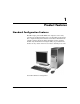
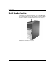
1 Product Features Standard Configuration Features The HP Compaq Convertible Minitower computer can be easily converted to a desktop. Features may vary depending on the model. For a complete listing of the hardware and software installed in the computer, run the diagnostic utility (included on some computer models only). Instructions for using the utility are provided in the Troubleshooting Guide on the Documentation and Diagnostics CD. Convertible Minitower Configuration Hardware Reference Guide www.hp.
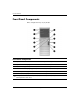
Product Features Front Panel Components Drive configuration may vary by model.
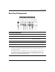
Product Features Rear Panel Components Rear Panel Components 1 Power Cord Connector 7 l Parallel Connector PS/2 Mouse Connector (green) 8 c Monitor Connector 9 k Line-Out Connector for powered 2 b 3 a PS/2 Keyboard Connector (purple) audio devices (green) 4 o Universal Serial Bus (USB) - j Line-In Audio Connector (blue) 5 m Serial Connector q g Microphone Connector (pink) 6 n RJ-45 Network Connector ✎ Arrangement and number of connectors may vary by model.
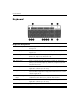
Product Features Keyboard Keyboard Components 1 Function Keys Perform special functions depending on the software application being used. 2 Editing Keys Includes the following: Insert, Home, Page Up, Delete, End, and Page Down. 3 Status Lights Indicate the status of the computer and keyboard settings (Num Lock, Caps Lock, and Scroll Lock). 4 Numeric Keys Work like a calculator keypad. 5 Arrow Keys Used to navigate through a document or Web site.
Product Features Using the Windows Logo Key Use the Windows Logo key in combination with other keys to perform certain functions available in the Windows operating system. Refer to the “Keyboard” section to identify the Windows Logo key.
Product Features Serial Number Location Each computer has a unique serial number and a product ID number that are located on the top cover of the computer. Keep these numbers available for use when contacting customer service for assistance. Serial Number and Product ID Location 1–6 www.hp.
Product Features Changing from a Minitower to a Desktop Configuration 1. If you have locked the Smart Cover Lock, restart the computer and enter Computer Setup to unlock the lock. 2. Turn off the computer properly through the operating system and turn off any external devices. Disconnect the power cord from the power outlet and disconnect any external devices. 3. Remove the computer access panel as described in the “Removing the Computer Access Panel” section. 4.
Product Features 7. Before you reinstall each drive into the chassis, turn the drive so that it is perpendicular to the internal 3.5-inch drive. The drive should be parallel to the green latch drive bracket. Installing a Drive in the Desktop Configuration 8. Gently slide the drive into the uppermost available bay until it snaps into place. When the drive is properly inserted, the drivelock will secure it. Repeat this step for each drive. Ä CAUTION: The bottom 5.
Product Features 11. Reposition the bezel blanks within the subpanel in the proper orientation for the desktop configuration. 12. Reposition the subpanel (rotate it 90°) with the logo at the bottom, then snap it back into the bezel. Changing from a Minitower to a Desktop Configuration 13. Replace the front bezel and computer access panel. 14. Reconnect the external equipment. 15. If you normally lock the Smart Cover Lock, use Computer Setup to relock the lock and enable the Smart Cover Sensor.
Product Features Changing from a Desktop to a Minitower Configuration 1. If you have locked the Smart Cover Lock, restart the computer and enter Computer Setup to unlock the lock. 2. Turn off the computer properly through the operating system and turn off any external devices. Disconnect the power cord from the power outlet and disconnect any external devices. 3. Remove the computer access panel as described in the “Removing the Computer Access Panel” section. 4.
Product Features 7. Before you reinstall each drive into the chassis, turn it so that it is in the same orientation as the internal 3.5-inch drive. The bottom of the drive should be parallel to the yellow drivelock. Installing a Drive in the Minitower Configuration 8. Gently slide the drive into the uppermost available bay until it snaps into place. When the drive is properly inserted, the drivelock will secure it. Repeat this step for each drive. Ä CAUTION: The bottom 5.
Product Features 10. Remove the bezel subpanel as described in the “Removing Bezel Blanks” section. Ä CAUTION: Hold the subpanel straight when you pull it away from the front bezel. Pulling the subpanel away at an angle could damage the pins that align it within the front bezel. 11. Reposition the bezel blanks within the subpanel in the proper orientation for the minitower configuration. 12. Reposition the subpanel (rotate it 90°) with the logo at the bottom, then snap it back into the bezel.
2 Hardware Upgrades Serviceability Features The computer includes features that make it easy to upgrade and service. No tools are needed for most of the installation procedures described in this chapter. Warnings and Cautions Before performing upgrades be sure to carefully read all of the applicable instructions, cautions, and warnings in this guide.
Hardware Upgrades Smart Cover Lock Smart Cover Lock is an optional feature included on some ✎ The models only. The Smart Cover Lock is a software-controllable cover lock, controlled by the setup password. This lock prevents unauthorized access to the internal components. The computer ships with the Smart Cover Lock in the unlocked position. For more information about locking the Smart Cover Lock, refer to the Desktop Management Guide on the Documentation and Diagnostics CD.
Hardware Upgrades To open the access panel with the Smart Cover Lock engaged: 1. Turn off the computer properly through the operating system and turn off any external devices. 2. Disconnect the power cord from the power outlet, and disconnect any external devices. 3. Using the Smart Cover FailSafe Key, remove the two tamper-proof screws that secure the Smart Cover Lock to the chassis. Removing the Smart Cover Lock Screws 4. Remove the access panel. Refer to “Removing the Computer Access Panel.
Hardware Upgrades Removing the Computer Access Panel 1. If you have locked the Smart Cover Lock, restart the computer and enter Computer Setup to unlock the lock. 2. Turn off the computer properly through the operating system and turn off any external devices. 3. Disconnect the power cord from the power outlet, and disconnect any external devices.
Hardware Upgrades Replacing the Computer Access Panel 1. Lay the computer down on its large base for greater stability. 2. Align the tabs on the access panel with the slots on the chassis and slide the access panel forward until it locks into place. Replacing the Computer Access Panel 3. If you normally lock the Smart Cover Lock, use Computer Setup to relock the lock and enable the Smart Cover Sensor. Hardware Reference Guide www.hp.
Hardware Upgrades Removing the Front Bezel 1. If you have locked the Smart Cover Lock, restart the computer and enter Computer Setup to unlock the lock. 2. Turn off the computer properly through the operating system and turn off any external devices. Disconnect the power cord from the power outlet and disconnect any external devices. 3. Remove the computer access panel. 4. Push up on the two release tabs 1, then rotate the front bezel away from the chassis to release it 2.
Hardware Upgrades Replacing the Front Bezel When replacing the front bezel, ensure that the bottom hinge points are properly placed in the chassis 1 and rotate the front bezel back into its original position 2. Replacing the Front Bezel Hardware Reference Guide www.hp.
Hardware Upgrades Removing Bezel Blanks 1. If you have locked the Smart Cover Lock, restart the computer and enter Computer Setup to unlock the lock. 2. Turn off the computer properly through the operating system and turn off any external devices. Disconnect the power cord from the power outlet and disconnect any external devices. 3. Remove the computer access panel then remove the front bezel. 4.
Hardware Upgrades Installing Additional Memory The computer comes with double data rate 2 synchronous dynamic random access memory (DDR2-SDRAM) dual inline memory modules (DIMMs). DIMMs The memory sockets on the system board can be populated with up to four industry-standard DIMMs. These memory sockets are populated with at least one preinstalled DIMM. To achieve the maximum memory support, you can populate the system board with up to 4GB of memory configured in a high-performing dual channel mode.
Hardware Upgrades Populating DIMM Sockets The system will automatically operate in single channel mode, dual channel Asymmetric mode, or a higher-performing dual channel Interleaved mode, depending on how the DIMMs are installed. ■ The system will operate in single channel mode if the DIMM sockets are populated in one channel only.
Hardware Upgrades DIMM Socket Locations Hardware Reference Guide Item Description Socket Color 1 DIMM socket XMM1, Channel A Black 2 DIMM socket XMM2, Channel A White 3 DIMM socket XMM3, Channel B Black 4 DIMM socket XMM4, Channel B White www.hp.
Hardware Upgrades Installing DIMMs Ä CAUTION: The memory module sockets have gold metal contacts. When upgrading the memory, it is important to use memory modules with gold metal contacts to prevent corrosion and/or oxidation resulting from having incompatible metals in contact with each other. Ä CAUTION: Static electricity can damage the electronic components of the computer or optional cards.
Hardware Upgrades 6. Open both latches of the memory module socket 1, and insert the memory module into the socket 2. Installing a DIMM module can be installed in only one way. Match the notch ✎ Aonmemory the module with the tab on the memory socket. maximum performance, populate the sockets so that the memory ✎ For capacity of Channel A is equal to the memory capacity of Channel B.
Hardware Upgrades 8. Repeat steps 6 and 7 for to install any additional modules. 9. Replace the access panel. 10. If you normally lock the Smart Cover Lock, use Computer Setup to relock the lock and enable the Smart Cover Sensor. The computer should automatically recognize the additional memory the next time you turn on the computer. 2–14 www.hp.
Hardware Upgrades Installing or Removing an Expansion Card The computer has two PCI expansion slots that can accommodate an expansion card up to 17.46 cm (6.875 inches) in length. The computer also has one PCI Express x1 expansion slot and one PCI Express x16 expansion slot.
Hardware Upgrades To install an expansion card: 1. If you have locked the Smart Cover Lock, restart the computer and enter Computer Setup to unlock the lock. 2. Turn off the computer properly through the operating system and turn off any external devices. 3. Disconnect the power cord from the power outlet, then disconnect any external devices. 4. Remove the computer access panel. 5.
Hardware Upgrades 7. Before installing an expansion card, remove the expansion slot cover or the existing expansion card. a. If you are installing an expansion card in a vacant socket, remove the appropriate expansion slot cover on the back of the chassis. Lift the expansion slot cover from the expansion slot. Removing an Expansion Slot Cover Hardware Reference Guide www.hp.
Hardware Upgrades b. If you are removing a standard PCI card, hold the card at each end and carefully rock it back and forth until the connectors pull free from the socket. Lift the card straight up to remove it. Be sure not to scrape the card against other components. removing an installed expansion card, disconnect any cables ✎ Before that may be attached to the expansion card. Removing a Standard PCI Expansion Card 2–18 www.hp.
Hardware Upgrades c. If you are removing a PCI Express x16 card, pull the retention arm on the back of the expansion socket away from the card and carefully rock the card back and forth until the connectors pull free from the socket. Lift the card straight up to remove it. Be sure not to scrape the card against other components. removing an installed expansion card, disconnect any cables ✎ Before that may be attached to the expansion card. Removing a PCI Express x16 Expansion Card 8.
Hardware Upgrades 10. To install a new expansion card, slide the bracket on the end of the card down into the slot on the back of the chassis and press the card down firmly into the socket on the system board. Installing an Expansion Card you install an expansion card, make sure you press firmly on ✎ When the card so that the whole connector seats properly in the expansion card socket. 11. Close the expansion card retention latch, making sure that it snaps firmly into place. 12.
Hardware Upgrades 15. Reconfigure the computer, if necessary. Refer to the Computer Setup (F10) Utility Guide on the Documentation and Diagnostics CD for instructions about using Computer Setup. Drive Positions Desktop and Minitower Drive Positions 1 Three 5.25-inch, half-height bays for optional drives (an optional hard drive mounting bracket for these drive bays is available from HP) 2 One standard 3.5-inch, one-third height bay (1.44-MB diskette drive shown)* 3 Two internal 3.
Hardware Upgrades Installing Additional Drives The computer supports up to six drives that may be installed in various configurations. When installing additional drives, follow these guidelines: 2–22 ■ The primary Serial ATA (SATA) hard drive should be connected to the primary SATA controller on the system board labeled P60 SATA 0. Connect a second SATA hard drive to the secondary SATA controller labeled P61 SATA 1. Connect a third SATA drive to P62 SATA 2 and a fourth SATA drive to P63 SATA 3.
Hardware Upgrades Ä■ CAUTION: To prevent loss of work and damage to the computer or drive: Hardware Reference Guide If you are inserting or removing a hard drive, shut down the operating system properly, turn off the computer, and unplug the power cord. Do not remove a hard drive while the computer is on or in standby mode. ■ Before handling a drive, ensure that you are discharged of static electricity. While handling a drive, avoid touching the connector.
Hardware Upgrades Installing an Optical or other Removable Storage Device optical drive is a CD-ROM, CD-R/RW, DVD-ROM, DVD+R/RW, ✎ An or CD-RW/DVD Combo drive. 1. If you have locked the Smart Cover Lock, restart the computer and enter Computer Setup to unlock the lock. 2. Turn off the computer properly through the operating system and turn off any external devices. Disconnect the power cord from the power outlet and remove the computer access panel. 3. Remove the front bezel. 4.
Hardware Upgrades Installing a 5.25-Inch Drive on a Minitower (top) and Desktop (bottom) 5. Install the drive in the desired drive bay by sliding it into the front of the drive cage 2; the drivelock automatically secures the drive in the bay. Ä CAUTION: The bottom 5.25-inch drive bay has a shorter depth than the upper two bays. The bottom bay supports a drive that is no more than 17 cm (6.7 inches) in depth, including the cables that attach to the back of the drive.
Hardware Upgrades you are installing a third optional drive in the bottom 5.25-inch ✎ Ifdrive bay, you must also install an expansion card with an IDE controller and data cable (not supplied) because the secondary IDE controller supports only two drives. a third optional drive, you may need to remove ✎ Iftheyoustraparethatinstalling bundles the extra power connectors. 6. Connect the power and signal cables to the rear of the drive. Connecting the Drive Cables 7.
Hardware Upgrades Installing a SATA Hard Drive into a 3.5-inch Drive Bay replacing a hard drive, make sure to back up the data on the ✎ Ifoldyouhardaredrive before removing it so that you can install the data onto the new hard drive. does not support connecting both SATA and 3.5-inch PATA hard ✎ HP drives on the same system. To install a hard drive in a 3.5-inch drive bay: 1. If you have locked the Smart Cover Lock, restart the computer and enter Computer Setup to unlock the lock. 2.
Hardware Upgrades 4. Slide the hard drive down into the drive cage; the drivelock automatically secures the drive in the bay. Installing a Hard Drive into the Hard Drive Bay Ä 2–28 CAUTION: Make sure the guide screws line up with the guide slots in the drive cage. The use of unnecessary force when installing any drive into the drive bay may result in damage to the drive. www.hp.
Hardware Upgrades 5. Connect the power cable 1 and data cable 2 to the hard drive. Connecting the Power Cable and Data Cable to a SATA Hard Drive 6. Connect the opposite end of the data cable to the appropriate system board connector. has only one SATA hard drive, you must connect the ✎ Ifhardyourdrivesystem to the connector labeled P60 SATA 0 first to avoid any hard drive performance problems. If you are adding a second hard drive, connect the data cable to the system board connector labeled P61 SATA 1.
Hardware Upgrades replaced the primary hard drive, insert the Restore Plus! CD ✎ Ifto you restore the operating system, software drivers, and any software applications that were preinstalled on the computer. Follow the instructions in the guide included with the Restore Plus! CD. When the restore process has completed, reinstall any personal files that you backed up before replacing the hard drive. Removing a Drive from the Drive Bay 1.
Hardware Upgrades 5. Remove the drive from the drive bay as follows: ❏ To remove an optical drive in the desktop configuration, press down on the yellow drivelock mechanism 1 and slide the drive from the drive bay 2. Removing an Optical Drive in the Desktop Configuration Hardware Reference Guide www.hp.
Hardware Upgrades ❏ To remove a diskette drive or an optical drive in the minitower configuration, pull up on the green drivelock mechanism 1 for that specific drive and slide the drive from the drive bay 2. Removing a Diskette Drive or an Optical Drive in the Minitower Configuration (Optical Drive Shown) 2–32 www.hp.
Hardware Upgrades ❏ To remove a hard drive, pull up on the green hard drive drivelock mechanism 1 for that drive and slide the drive from the drive bay 2. Removing a Hard Drive 6. Store the removed drive in anti-static packaging. Hardware Reference Guide www.hp.
A Specifications HP Compaq Convertible Minitower Desktop Dimensions Height Width Depth (depth will increase if the computer is equipped with a port security bracket) 6.6 in 17.65 in 17.8 in 16.7 cm 44.8 cm 45.2 cm 17.65 in 6.6 in 17.8 in 44.8 cm 16.7 cm 45.2 cm 35 lb 15.9 kg 100 lb 45.
Specifications HP Compaq Convertible Minitower (Continued) Heat Dissipation Maximum Typical (idle) 1,916 BTU/hr 375 BTU/hr 230V 115V Power Supply Operating Voltage Range* Rated Voltage Range Rated Line Frequency Power Output Rated Input Current (maximum)* 483 kg-cal/hr 95 kg-cal/hr 90-264 VAC 100-240 VAC 50-60 Hz 90-264 VAC 100-240 VAC 50-60 Hz 365 W 365 W 6A @ 100 VAC 3A @ 200 VAC *This system utilizes an active power factor corrected power supply.
B Battery Replacement The battery that comes with the computer provides power to the real-time clock. When replacing the battery, use a battery equivalent to the battery originally installed in the computer. The computer comes with a 3-volt lithium coin cell battery. lifetime of the lithium battery can be extended by plugging the ✎ The computer into a live AC wall socket. The lithium battery is only used when the computer is NOT connected to AC power.
Battery Replacement Ä CAUTION: Static electricity can damage the electronic components of the computer or optional equipment. Before beginning these procedures, ensure that you are discharged of static electricity by briefly touching a grounded metal object. 1. If you have locked the Smart Cover Lock, use Computer Setup to unlock the lock and disable the Smart Cover Sensor. 2. Turn off the computer properly through the operating system, then turn off any external devices.
Battery Replacement Type 2 a. To release the battery from its holder, squeeze the metal clamp that extends above one edge of the battery. When the battery pops up, lift it out 1. b. To insert the new battery, slide one edge of the replacement battery under the holder’s lip with the positive side up. Push the other edge down until the clamp snaps over the other edge of the battery 2. Removing and Replacing a Coin Cell Battery (Type 2) Hardware Reference Guide www.hp.
Battery Replacement Type 3 a. Pull back on the clip 1 that is holding the battery in place, and remove the battery 2. b. Insert the new battery and position the clip back into place. Removing a Coin Cell Battery (Type 3) the battery has been replaced, use the following steps to ✎ After complete this procedure. 5. Replace the computer access panel. 6. Plug in the computer and turn on power to the computer. 7. Reset the date and time, your passwords, and any special system setups, using Computer Setup.
C Security Lock Provisions information on data security features, refer to the Computer Setup ✎ For (F10) Utility Guide and the Desktop Management Guide on the Documentation and Diagnostics CD and the HP ProtectTools Security Manager Guide (some models) at www.hp.com. Installing a Security Lock The security locks displayed below and on the following pages can be used to secure the Convertible Minitower computer. Cable Lock Installing a Cable Lock Hardware Reference Guide www.hp.
Security Lock Provisions Padlock I Installing a Padlock C–2 www.hp.
Security Lock Provisions Universal Chassis Clamp Lock Without Security Cable 1. Thread the keyboard and mouse cables through the lock. Hardware Reference Guide www.hp.
Security Lock Provisions 2. Screw the lock to the chassis using the screw provided. 3. Insert the plug into the lock 1 and push the button in 2 to engage the lock. Use the key provided to disengage the lock. C–4 www.hp.
Security Lock Provisions With Security Cable 1. Fasten the security cable by looping it around a stationary object. 2. Thread the keyboard and mouse cables through the lock. Hardware Reference Guide www.hp.
Security Lock Provisions 3. Screw the lock to the chassis using the screw provided. 4. Insert the plug end of the security cable into the lock 1 and push the button in 2 to engage the lock. Use the key provided to disengage the lock. C–6 www.hp.
D Electrostatic Discharge A discharge of static electricity from a finger or other conductor may damage system boards or other static-sensitive devices. This type of damage may reduce the life expectancy of the device. Preventing Electrostatic Damage To prevent electrostatic damage, observe the following precautions: ■ Avoid hand contact by transporting and storing products in static-safe containers. ■ Keep electrostatic-sensitive parts in their containers until they arrive at static-free workstations.
Electrostatic Discharge ■ Use heelstraps, toestraps, or bootstraps at standing workstations. Wear the straps on both feet when standing on conductive floors or dissipating floor mats. ■ Use conductive field service tools. ■ Use a portable field service kit with a folding static-dissipating work mat. If you do not have any of the suggested equipment for proper grounding, contact an HP authorized dealer, reseller, or service provider.
E Computer Operating Guidelines, Routine Care and Shipping Preparation Computer Operating Guidelines and Routine Care Follow these guidelines to properly set up and care for the computer and monitor: Hardware Reference Guide ■ Keep the computer away from excessive moisture, direct sunlight, and extremes of heat and cold. For information about the recommended temperature and humidity ranges for the computer, refer to Appendix A, “Specifications” in this guide.
Computer Operating Guidelines, Routine Care and Shipping Preparation ■ Turn off the computer before you do either of the following: ❏ Wipe the exterior of the computer with a soft, damp cloth as needed. Using cleaning products may discolor or damage the finish. ❏ Occasionally clean the air vents on all vented sides of the computer. Lint, dust, and other foreign matter can block the vents and limit the airflow.
Computer Operating Guidelines, Routine Care and Shipping Preparation Shipping Preparation Follow these suggestions when preparing to ship the computer: 1. Back up the hard drive files on PD discs, tape cartridges, CDs, or diskettes. Be sure that the backup media is not exposed to electrical or magnetic impulses while stored or in transit. hard drive locks automatically when the system power is ✎ The turned off. 2. Remove and store any program diskettes from the diskette drives. 3.
Index A D access panel locking and unlocking 2–2, C–1 removing 2–4 application key 1–4 audio connectors 1–2, 1–3 desktop configuration 1–7 DIMMs See memory diskette drive features 1–2 installing 2–24 drive positions 2–21 DVD-ROM drive See optical drive B battery replacement B–1 bezel See front bezel E C CD-ROM drive See optical drive changing computer configuration 1–7, 1–10 components front panel 1–2 keyboard 1–4 rear panel 1–3 computer access panel 2–4 changing from desktop to minitower 1–10 changin
Index G M guidelines computer operating E–1 memory Asymetric mode 2–10 capacity 2–9, 2–10, 2–13 identifying sockets 2–11 installing 2–9 Interleaved mode 2–10 populating sockets 2–10 single channel mode 2–10 specifications 2–9 microphone connector 1–2, 1–3 minitower configuration 1–10 monitor, connecting 1–3 mouse connector 1–3 special functions 1–5 H hard drive activity light 1–2 connecting SATA cables 2–29 guide screws 2–27 installing SATA 2–27 restoring 2–30 headphone connector 1–2 headphone line-out
Index removing battery B–1 bezel blanks 2–8 computer access panel 2–4 drives from drive bay 2–30 expansion card 2–15 expansion slot cover 2–17 front bezel 2–6 Smart Cover Lock 2–2 RJ-45 connector 1–3 S SATA connecting cables 2–29 installing hard drive 2–27 security cable lock C–1 chassis clamp lock C–3 padlock C–2 Smart Cover Lock 2–2 serial connector 1–3 Hardware Reference Guide serial number location 1–6 shipping preparation E–3 Smart Cover Lock and FailSafe Key 2–2 specifications computer A–1 memory