Hardware Reference Guide HP Compaq Business Desktops d330 Microtower Model Document Part Number: 323353-002 September 2003 This guide provides basic information for upgrading this computer model.
© Copyright 2003 Hewlett-Packard Development Company, L.P. The information contained herein is subject to change without notice. Microsoft, MS-DOS, Windows, and Windows NT are trademarks of Microsoft Corporation in the U.S. and other countries. Intel, Pentium, Intel Inside, and Celeron are trademarks of Intel Corporation in the U.S. and other countries. Adobe, Acrobat, and Acrobat Reader are trademarks or registered trademarks of Adobe Systems Incorporated.
Contents 1 Product Features Standard Configuration Features. . . . . . . . . . . . . . . . . . . . . . . . . . . . . . . . . . . . . . . . . . Front Panel Components . . . . . . . . . . . . . . . . . . . . . . . . . . . . . . . . . . . . . . . . . . . . . . . . Rear Panel Components . . . . . . . . . . . . . . . . . . . . . . . . . . . . . . . . . . . . . . . . . . . . . . . . Easy Access Keyboard . . . . . . . . . . . . . . . . . . . . . . . . . . . . . . . . . . . . . . . . . . . . . . . . .
Contents A Specifications B PATA Hard Drive Installation Guidelines Using the Cable-Select Feature with Parallel ATA (PATA) Devices. . . . . . . . . . . . . . B–1 Guidelines for Installing PATA Drives . . . . . . . . . . . . . . . . . . . . . . . . . . . . . . . . . B–2 C Battery Replacement D Security Lock Provisions Installing a Security Lock . . . . . . . . . . . . . . . . . . . . . . . . . . . . . . . . . . . . . . . . . . . . . . . D–1 E Port Security Bracket Installing the Port Security Bracket. .
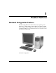
1 Product Features Standard Configuration Features The HP Compaq Microtower features may vary depending on the model. For a complete listing of the hardware and software installed in the computer, run the Diagnostics for Windows utility. Instructions for using this utility are provided in the Troubleshooting Guide on the Documentation Library CD. Microtower Configuration Hardware Reference Guide www.hp.
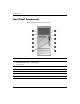
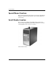
Product Features Front Panel Components Drive configuration may vary by model.
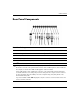
Product Features Rear Panel Components Rear Panel Components 1 Power Cord Connector 7 n RJ-45 Network Connector 2 Voltage Select Switch 8 l Parallel Connector PS/2 Mouse Connector 9 c Monitor Connector 3 b 4 a PS/2 Keyboard Connector - h Headphone/Line-Out Connector 5 o Universal Serial Bus (USB) q j Line-In Audio Connector 6 m w g Serial Connector Microphone Connector ✎ Arrangement and number of connectors may vary by model.
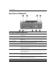
Product Features Easy Access Keyboard Easy Access Keyboard Components 1 Function Keys Perform special functions depending on the software application being used. 2 Easy Access Buttons Provide quick access to specific Internet destinations. 3 Editing Keys Includes the following: Insert, Home, Page Up, Delete, End, and Page Down. 4 Status Lights Indicate the status of the computer and keyboard settings (Num Lock, Caps Lock, and Scroll Lock). 5 Numeric Keys Work like a calculator keypad.
Product Features Customizing the Easy Access Buttons All Easy Access buttons can be reprogrammed to open any software application or data file on the hard drive, or any Internet address. To reprogram the Easy Access buttons, complete the following steps: 1. Double-click the keyboard icon in the notification area (lower right corner) of the Windows taskbar. The Keyboard Properties dialog box is displayed. 2. Click the Help button on the Keyboard Properties dialog box for instructions.
Product Features Special Mouse Functions Most software applications support the use of a mouse. The functions assigned to each mouse button depend on the software applications you are using. Serial Number Location Each computer has a unique serial number that is located on the top cover of the computer. Keep this number available for use when contacting HP customer service for assistance. Serial Number Location 1–6 www.hp.
2 Hardware Upgrades Serviceability Features The Microtower computer includes features that make it easy to upgrade and service. No tools are needed for most of the installation procedures described in this chapter. Warnings and Cautions Before performing upgrades be sure to carefully read all of the applicable instructions, cautions, and warnings in this guide.
Hardware Upgrades Removing the Computer Access Panel and Front Bezel To remove the computer access panel: 1. If you have locked the Smart Cover Lock, use Computer Setup to unlock the lock. Refer to the Desktop Management Guide on the Documentation Library CD for more information about the Smart Cover Lock. you enable the Smart Cover Lock and cannot disable the lock ✎ Ifthrough Computer Setup, you will need a Smart Cover FailSafe Key to remove the screws that retain the lock and open the computer cover.
Hardware Upgrades Ä CAUTION: Before removing the computer access panel, ensure that the computer is turned off and that the power cord is disconnected from the electrical outlet. 4. Loosen the captive thumbscrew 1 that secures the access panel to the computer chassis. 5. Slide the access panel 2 back about 1 inch (2.5 cm), then lift it off the unit. may want to lay the computer on its side to install internal parts. ✎ You Be sure the side with the access panel and pull grip is facing up.
Hardware Upgrades 6. To remove the front bezel, press down on all three tabs on the left side of the bezel 1 then rotate the bezel off the chassis 2, beginning with the left side then the right side. Removing the Front Bezel 2–4 www.hp.
Hardware Upgrades Installing Additional Memory The computer comes with double data rate synchronous dynamic random access memory (DDR-SDRAM) dual inline memory modules (DIMMs). DIMMs The memory sockets on the system board can be populated with up to four industry-standard DIMMs. These memory sockets are populated with at least one preinstalled DIMM. To achieve the maximum memory support, you can populate the system board with up to 4GB of memory configured in a high-performing dual channel mode.
Hardware Upgrades Memory Frequency Required Processor Bus Frequency 266 MHz 400 MHz, 533 MHz, or 800 MHz 333 MHz 533 MHz or 800 MHz 400 MHz 800 MHz If a memory frequency is paired with an unsupported processor bus frequency, the system will run at the highest supported memory speed. For example, if a 333 MHz DIMM is paired with a 400 MHz processor bus, the system will run at 266 MHz, the highest supported memory speed. ✎ The system will not start if you install unsupported DIMMs.
Hardware Upgrades There are four DIMM sockets on the system board, with two sockets per channel. The sockets are labeled XMM1, XMM2, XMM3, and XMM4. Sockets XMM1 and XMM2 operate in memory channel A. Sockets XMM3 and XMM4 operate in memory channel B. DIMM Socket Locations Hardware Reference Guide Item Description Socket Color 1 DIMM socket XMM1, Channel A Black 2 DIMM socket XMM2, Channel A Blue 3 DIMM socket XMM3, Channel B Black 4 DIMM socket XMM4, Channel B Blue www.hp.
Hardware Upgrades Installing DDR-SDRAM DIMMs Ä CAUTION: The memory module sockets have gold metal contacts. When upgrading the memory, it is important to use memory modules with gold metal contacts to prevent corrosion and/or oxidation resulting from having incompatible metals in contact with each other. Ä CAUTION: Static electricity can damage the electronic components of the computer or optional cards.
Hardware Upgrades Installing a DIMM module can be installed in only one way. Match the notch ✎ Aonmemory the module with the tab on the memory socket. 5. Push the module down into the socket, ensuring that the module is fully inserted and properly seated. Make sure the latches are in the closed position 3. 6. Repeat steps 4 and 5 to install any additional modules. 7. Replace the access panel. 8.
Hardware Upgrades Replacing or Upgrading a Drive The computer supports up to six drives that may be installed in various configurations. This section describes the procedure for replacing or upgrading the storage drives. A Torx screwdriver is needed to replace the guide screws on a drive. Ä CAUTION: Make sure you back up your personal files on the hard drive to an external storage device, such as a CD, before removing the hard drive. Failure to do so will result in data loss.
Hardware Upgrades Removing a Drive 1. If you have locked the Smart Cover Lock, use Computer Setup to unlock the lock. 2. Turn off the computer properly through the operating system and turn off any external devices. Disconnect the power cord from the power outlet and disconnect any external devices. 3. Remove the access panel and front bezel. 4. Disconnect the power and data cables from the back of the drive, as indicated in the following illustrations.
Hardware Upgrades Disconnecting the Diskette Drive Cables Disconnecting the Hard Drive Cables (connectors may vary) 2–12 www.hp.
Hardware Upgrades 5. A latch drive bracket with release tabs secures the drives in the drive bay. Lift the release tab on the latch drive bracket 1 for the drive you want to remove, then slide the drive from its drive bay 2. Removing the Drives 6. Remove the four guide screws (two on each side) from the old drive. You will need these screws to install a new drive. Hardware Reference Guide www.hp.
Hardware Upgrades Replacing a Drive Ä■ CAUTION: To prevent loss of work and damage to the computer or drive: If you are inserting or removing a hard drive, shut down the operating system properly, then turn off the computer. Do not remove a hard drive while the computer is on or in standby mode. ■ Before handling a drive, ensure that you are discharged of static electricity. While handling a drive, avoid touching the connector.
Hardware Upgrades 1. Install the four guide screws (two on each side) that were removed from the old drive into the new drive. The screws help guide the drive into its proper position in the bay. Extra guide screws are provided on the front of the chassis under the front bezel. are a total of eight extra guide screws on the front of the chassis ✎ There under the bezel. Four have 6-32 standard threads and four have M3 metric threads. Standard screws are used for hard drives and have a silver finish.
Hardware Upgrades 3. Reconnect the power and data cables to the drive as indicated in the following illustrations. Reconnecting the Optical Drive Cables Reconnecting the Diskette Drive Cables 2–16 www.hp.
Hardware Upgrades Reconnecting the Hard Drive Cables (connectors may vary) Hardware Reference Guide www.hp.
Hardware Upgrades 4. If installing a new hard drive, connect the power and data cables to the system board. has only one SATA hard drive, you must connect the ✎ Ifhardyourdrivesystem to the connector labeled SATA 0 first to avoid any hard drive performance problems. Hard Drive Connector Locations 1 SATA hard drive connector 2 PATA hard drive connector 5. Complete the procedure described in the “Reassembling the Computer” section of this chapter. 2–18 www.hp.
Hardware Upgrades 6. Turn on the computer. If you have installed a PATA hard drive that is not automatically recognized by the computer, see Appendix B, “PATA Hard Drive Installation Guidelines.” If you have installed a SATA hard drive that is not automatically recognized by the computer, refer to the white paper “Implementation of Serial ATA on HP Business Desktops” for operating system instructions. The white paper is located at www.hp.com/support.
Hardware Upgrades 4. On the rear of the computer, a sliding slot cover lock secures the expansion card brackets and expansion slot covers in place. Slide the slot cover lock away from the brackets so that they are no longer secured by the lock. Releasing the Slot Cover Lock 5. Inside the computer, locate the correct vacant expansion slot on the system board and remove the corresponding slot cover. 2–20 www.hp.
Hardware Upgrades 6. If removing an expansion card from a standard expansion socket, hold the card at each end, and carefully rock it back and forth until the connectors pull free from the socket. Pull the expansion card straight up from the socket 1 then away from the inside of the chassis 2 to release it from the chassis frame. Be sure not to scrape the card against the other components. Removing an Expansion Card from a Standard Expansion Socket Hardware Reference Guide www.hp.
Hardware Upgrades 7. If removing an AGP card from an AGP expansion socket with a retention mechanism, pull the retention arm away from the socket then carefully rock the card back and forth until the connectors pull free from the socket. Pull the expansion card straight up from the socket then away from the inside of the chassis to release it from the chassis frame. Be sure not to scrape the card against the other components. Removing an AGP Card from a Socket with a Retention Mechanism 8.
Hardware Upgrades 9. If replacing or adding a new expansion card, hold the card just above the expansion slot on the system board then move the card toward the rear of the chassis so that the bracket on the card is aligned with the open slot on the rear of the chassis 1. Gently press the card straight down into the expansion slot on the system board 2.
Hardware Upgrades 11. While holding the expansion card bracket against the chassis, slide the slot cover lock down toward the expansion card brackets and slot covers to secure them in place. Securing the Expansion Cards and Slot Covers 12. Complete the procedure described in the “Reassembling the Computer” section of this chapter. 2–24 www.hp.
Hardware Upgrades Reassembling the Computer 1. Position the chassis in the upright position. Insert the three hooks on the right side of the bezel 1 into the rectangular holes on the chassis then rotate the bezel into place so that the three tabs on the left side of the bezel snap into the slots on the chassis 2. Replacing the Front Bezel Hardware Reference Guide www.hp.
Hardware Upgrades 2. Place the side access panel in the proper position on the chassis and slide it into place 1. Ensure that the hole for the thumbscrew is aligned with the hole in the chassis and tighten the thumbscrew 2. Replacing the Side Access Panel 2–26 www.hp.
Hardware Upgrades 3. Reconnect the power cable to the computer 1 and plug the cable into an electrical outlet 2. Reconnecting the Power Cable 4. Reconnect all peripheral devices to the computer. Å WARNING: To reduce the risk of electrical shock, fire, or damage to the equipment, do not plug telecommunications or telephone connectors into the network interface controller (NIC) ports. 5. Turn on the computer by pressing the power button. 6.
Hardware Upgrades 2–28 www.hp.
A Specifications HP Compaq d330 Microtower Microtower Dimensions Height Width Depth (depth will increase if the computer is equipped with a port security bracket) Approximate Weight 14.5 in 6.88 in 16.5 in 36.8 cm 17.5 cm 42.0 cm 23.8 lb 10.
Specifications HP Compaq d330 Microtower (Continued) Input Voltage Switch Setting 115 V 230 V 90-132 VAC 100-127 VAC 50-60 Hz 180-264 VAC 200-240 VAC 50-60 Hz 240 W 240 W 6 A @100 VAC 3 A @ 200 VAC Power Supply Operating Voltage Range Rated Voltage Range Rated Line Frequency Power Output Rated Input Current (maximum) A–2 www.hp.
B PATA Hard Drive Installation Guidelines more information about Serial ATA (SATA) devices, refer to the ✎ For white paper “Implementation of Serial ATA on HP Business Desktops”. The white paper is located at www.hp.com/support. Using the Cable-Select Feature with Parallel ATA (PATA) Devices Optional drives are available from HP in kits that include a special drive cable.
PATA Hard Drive Installation Guidelines Guidelines for Installing PATA Drives When installing additional drives, follow these guidelines: ■ If using multiple devices, HP recommends that the devices be split between the primary and secondary channels for optimum performance. Use an additional cable to connect the additional device to the system board. ■ 80-conductor PATA cable: ❏ 18 inches maximum total length, 80-conductor cable with maximum spacing of 6 inches between Device 0 and Device 1.
PATA Hard Drive Installation Guidelines you have only one device, make sure to connect it to the Device 0 ✎ Ifconnector. If you connect it to the Device 1 connector, the system will not recognize the device and you may receive a “no fixed disk found” error message. Hardware Reference Guide www.hp.
PATA Hard Drive Installation Guidelines B–4 www.hp.
C Battery Replacement The battery that comes with the computer provides power to the real-time clock. When replacing the battery, use a battery equivalent to the battery originally installed in the computer. The computer comes with a 3-volt lithium coin cell battery. lifetime of the lithium battery can be extended by plugging the ✎ The computer into a live AC wall socket. The lithium battery is only used when the computer is NOT connected to AC power.
Battery Replacement Ä CAUTION: Static electricity can damage the electronic components of the computer or optional equipment. Before beginning these procedures, ensure that you are discharged of static electricity by briefly touching a grounded metal object. 1. If you have locked the Smart Cover Lock, use Computer Setup to unlock the lock and disable the Smart Cover Sensor. 2. Turn off the computer properly through the operating system, then turn off any external devices.
Battery Replacement Type 2 a. To release the battery from its holder, squeeze the metal clamp that extends above one edge of the battery. b. When the battery pops up, lift it out. Removing a Coin Cell Battery (Type 2) Hardware Reference Guide www.hp.
Battery Replacement c. To insert the new battery, slide one edge of the replacement battery under the holder’s lip with the positive side up. Push the other edge down until the clamp snaps over the other edge of the battery. Replacing a Coin Cell Battery (Type 2) the battery has been replaced, use the following steps to ✎ After complete this procedure. 5. Replace the computer access panel. 6. Plug in the computer and turn on power to the computer. 7.
D Security Lock Provisions Installing a Security Lock The security locks displayed below and on the following page can be used to secure the Microtower computer. Installing a Cable Lock Hardware Reference Guide www.hp.
Security Lock Provisions I Installing a Padlock D–2 www.hp.
E Port Security Bracket Installing the Port Security Bracket 1. Insert the tabs on the bottom half of the port security bracket into the slots on the back of the chassis 1 and rotate the bracket toward the chassis 2. Hardware Reference Guide www.hp.
Port Security Bracket 2. Connect the cables to the computer. E-2 www.hp.
Port Security Bracket 3. Position the top of the port security bracket over the cables 1 and rotate the the bracket into place 2. Hardware Reference Guide www.hp.
Port Security Bracket 4. The illustration below shows the proper installation. E-4 www.hp.
Port Security Bracket Removing the Port Security Bracket 1. Loosen the captive thumbscrew 1 that secures the access panel to the computer chassis. 2. Slide the access panel 2 back about 1 inch (2.5 cm), then lift it off the unit. Hardware Reference Guide www.hp.
Port Security Bracket 3. Push in on the tabs 1 and rotate the top of the bracket away from the computer 2. E-6 www.hp.
Port Security Bracket 4. Disconnect the cables from the computer. Hardware Reference Guide www.hp.
Port Security Bracket 5. Push on the tabs to release the bottom of the bracket from the chassis 1. Rotate the bracket away from the chassis 2. E-8 www.hp.
F Electrostatic Discharge A discharge of static electricity from a finger or other conductor may damage system boards or other static-sensitive devices. This type of damage may reduce the life expectancy of the device. Preventing Electrostatic Damage To prevent electrostatic damage, observe the following precautions: ■ Avoid hand contact by transporting and storing products in static-safe containers. ■ Keep electrostatic-sensitive parts in their containers until they arrive at static-free workstations.
Electrostatic Discharge ■ Use heelstraps, toestraps, or bootstraps at standing workstations. Wear the straps on both feet when standing on conductive floors or dissipating floor mats. ■ Use conductive field service tools. ■ Use a portable field service kit with a folding static-dissipating work mat. If you do not have any of the suggested equipment for proper grounding, contact an HP authorized dealer, reseller, or service provider.
G Routine Computer Care and Shipping Preparation Routine Computer Care Follow these suggestions to take care of the computer and monitor: Hardware Reference Guide ■ Operate the computer on a sturdy, level surface. Leave a 3-inch (7.6-cm) clearance at the back of the system unit and above the monitor to permit the required airflow. ■ Never operate the computer with the cover or side panel removed. ■ Never restrict the airflow into the computer by blocking the front vents or air intake.
Routine Computer Care and Shipping Preparation Optical Drive Precautions Be sure to observe the following guidelines while operating or cleaning the optical drive. Operation ■ Do not move the drive during operation. This may cause it to malfunction during reading. ■ Avoid exposing the drive to sudden changes in temperature, as condensation may form inside the unit. If the temperature suddenly changes while the drive is on, wait at least one hour before you turn off the power.
Routine Computer Care and Shipping Preparation Shipping Preparation Follow these suggestions when preparing to ship the computer: 1. Back up the hard drive files on PD discs, tape cartridges, CDs, or diskettes. Be sure that the backup media is not exposed to electrical or magnetic impulses while stored or in transit. hard drive locks automatically when the system power is ✎ The turned off. 2. Remove and store any program diskettes from the diskette drives. 3.
Routine Computer Care and Shipping Preparation G–4 www.hp.
Index A access panel removing 2–3 replacing 2–26 B backup files 2–10, 2–19 battery replacement C–1 C CD-R/RW drive installing 2–10 locating 2–10 CD-ROM drive installing 2–10 locating 2–10 components front panel 1–2 keyboard 1–4 rear panel 1–3 computer routine care G–1 security lock D–1 shipping preparation G–3 specifications A–1 D DDR-SDRAM 2–5 DIMMs 2–5 diskette drive activity light 1–2 eject button 1–2 Hardware Reference Guide installing 2–10 locating 2–10 drive positions 2–10 DVD-R/RW drive installi
Index I P installation drives 2–11, 2–14 expansion card 2–19 installing memory 2–5 PATA See hard drive PCI card See expansion card power button 1–2 cord 2–2, 2–27 light 1–2 K keyboard components 1–4 PS/2 port 1–3 L latch drive bracket 2–13 M memory dual channel mode 2–6 installing 2–5 locating sockets 2–6 specifications 2–5 microphone connector 1–2 mouse PS/2 connector 1–3 special functions 1–6 O optical drive ATA B–2 optical drives activity light 1–2 defined 1–2 eject button 1–2 installing 2–14 loc