Getting Started HP Compaq Business Notebook Series Document Part Number: 376311-001 November 2004 This guide explains how to set up your notebook hardware and software and begin using your notebook. Enhanced for Accessibility.
© Copyright 2004 Hewlett-Packard Development Company, L.P. Microsoft and Windows are U.S. registered trademarks of Microsoft Corporation. SD Logo is a trademark of its proprietor. The information contained herein is subject to change without notice. The only warranties for HP products and services are set forth in the express warranty statements accompanying such products and services. Nothing herein should be construed as constituting an additional warranty.
Contents 1 Hardware Setup Step 1: Identify the Setup Hardware . . . . . . . . . . . . . . . . 1–2 Step 2: Insert the Battery Pack . . . . . . . . . . . . . . . . . . . . . 1–4 Step 3: Connect the Modem . . . . . . . . . . . . . . . . . . . . . . . 1–5 Connecting the Modem to an RJ-11 Jack . . . . . . . . . 1–6 Connecting the Modem with an Adapter. . . . . . . . . . 1–7 Step 4: Open the Notebook . . . . . . . . . . . . . . . . . . . . . . . 1–8 Step 5: Connect the Notebook to External Power . . . . . .
Contents Protect the Notebook from Power Surges . . . . . . . . . 3–6 Use the Notebook Safely . . . . . . . . . . . . . . . . . . . . . . 3–7 Turn Off the Notebook Properly . . . . . . . . . . . . . . . . 3–8 Connect to the Internet . . . . . . . . . . . . . . . . . . . . . . . . . . . 3–9 Enable Communication Hardware. . . . . . . . . . . . . . . 3–9 Set Up Internet Service . . . . . . . . . . . . . . . . . . . . . . 3–10 Preview the Help and Support Guide. . . . . . . . . . . . . . .
1 Hardware Setup Ä CAUTION: To prevent file corruption and ensure that the correct drivers are installed: ■ Do not set up the notebook for the first time while the notebook is connected to an optional expansion product. ■ During the hardware and software setup procedures: ❏ Do not unplug the notebook from external power. ❏ Do not shut down the notebook or initiate Standby mode or Hibernation mode. ❏ Do not insert, remove, connect, or disconnect any device, cable, or cord, unless instructed to do so.
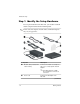
Hardware Setup Step 1: Identify the Setup Hardware To set up the notebook for the first time, you need the notebook and the components listed in the following table. cords, AC adapters, modem cables, and modem adapters ✎ Power may vary in appearance. Component Description 1 Connects the modem to a telephone jack or to a country-specific modem adapter. Modem cable (included with select models) modem cable has a 6-pin ✎ ARJ-11 telephone connector at each end.
Hardware Setup Component Description 3 AC adapter Converts AC power to DC power. 4 Network cable (not included) Connects the notebook to a network jack. network cable has an 8-pin ✎ ARJ-45 network connector at each end. 5 Country-specific modem adapter (included by region as required) Adapts the modem cable to a non-RJ-11 telephone jack. 6 Battery pack Provides power to the notebook when the notebook is not connected to external power.
Hardware Setup Step 2: Insert the Battery Pack Ä CAUTION: To avoid data loss when you turn on the notebook, make sure the battery pack is firmly seated. Ä CAUTION: To ensure that the correct drivers load and to prevent file corruption or damage to components, do not remove the battery pack until the notebook has been connected to external power. To insert the battery pack: 1. Turn the notebook upside down on a flat surface. 2.
Hardware Setup Step 3: Connect the Modem Å WARNING: To reduce the risk of electric shock, disconnect the modem from the telephone network before accessing an internal compartment of the notebook. Internal compartments include the memory compartment, the battery bay, and the hard drive bay. To connect the modem so that you can register your notebook and operating system during software setup: ■ Follow the instructions in this section for connecting the modem to an analog telephone line.
Hardware Setup Connecting the Modem to an RJ-11 Jack To connect the modem to an analog telephone line that has an RJ-11 telephone jack: 1. Turn the notebook display-side up on a flat surface near an RJ-11 telephone wall jack. 2. If your modem cable has noise suppression circuitry 1, which prevents interference with TV and radio reception, place the circuitry end of the cable near the notebook. 3. Plug the modem cable into the RJ-11 (modem) jack on the notebook 2. 4.
Hardware Setup Connecting the Modem with an Adapter To connect the modem to an analog telephone line that does not have an RJ-11 telephone wall jack: 1. Turn the notebook display-side up on a flat surface near a telephone wall jack. 2. If your modem cable has noise suppression circuitry 1, which prevents interference with TV and radio reception, place the circuitry end of the cable near the notebook. 3. Plug the modem cable into the RJ-11 (modem) jack on the notebook 2. 4.
Hardware Setup Step 4: Open the Notebook To open the notebook: 1. Place the notebook display-side up on a flat surface near an electrical outlet. 2. Press the display release button 1, and then lift the display 2.
Hardware Setup Step 5: Connect the Notebook to External Power To connect the notebook to external power: 1. Plug the AC adapter cable into the power connector 1. 2. Plug the power cord into the AC adapter 2, and then into an electrical outlet 3. The battery light is turned on and the battery pack begins to charge. cords, AC adapters, and electrical outlets may vary in ✎ Power appearance.
Hardware Setup Step 6: Charge the Battery Pack The battery pack begins to charge as soon as the notebook is connected to external power. Charge status is indicated by the battery light, which remains on while the battery pack is charging. The battery light is on while the battery pack is charging. It is recommended that you leave the notebook connected to external power until the battery pack is fully charged and the battery light is turned off.
Hardware Setup Step 7: Turn On the Notebook To turn on the notebook: » Press the power/standby button 1. The power/standby button light and the power/standby light on the front of the notebook 2 are turned on and you are prompted to begin software setup. power/standby button light and the power/standby light ✎ The display the same information. The power/standby button light is visible only when the notebook is open; the power/standby light is visible when the notebook is open or closed.
Hardware Setup If the notebook does not power up: 1–12 ■ Make sure the AC adapter is securely plugged into the notebook and an electrical outlet. ■ Make sure the electrical outlet is providing power. (To confirm that the outlet is providing power, plug another device into the outlet.) ■ If you have installed a battery pack, make sure the battery pack is firmly seated. ■ Refer to the Worldwide Telephone Numbers booklet (English only) included with the notebook to contact Customer Care.
2 Software Setup During software setup you can ■ Select regional preferences. ■ Accept license agreements. ■ Name your notebook. ■ Register online. ■ Create user accounts. If you prefer not to register your notebook during software setup, you can do so at any time after software setup is complete. You can also change or add any settings you select or skip during the setup process.
Software Setup Software setup begins when you respond to the setup prompt on the notebook screen. Ä CAUTION: If you are prompted to select an operating system language before the Welcome to Microsoft Windows window is displayed, choose carefully. On some models, the languages that you do not choose are deleted from the system and cannot be restored during software setup. ■ After you respond to the setup prompt, you must complete the entire setup process without interruption. Setup time varies.
Software Setup ■ To return to the previous window: Select the Back button in the lower-left corner of the window. (This button is unavailable on the first window, Welcome to Microsoft Windows.) ■ To skip a window without entering a preference: Select the Skip button in the lower-right corner of the window. (This button is unavailable on some windows.) To navigate in a window: » Slide your finger on the TouchPad 1 in the direction that you want to move the pointer.
Software Setup Select Your Regional Preferences The next 2 windows prompt you to confirm or select regional preferences. Regional preferences are preset for the country in which you purchased the notebook. ■ Dates and currency window—The operating system will format dates and currency according to the region and language preferences you confirm or select in the How should dates and currency appear? window. Notice that some languages include regional versions.
Software Setup Accept the End-User License Agreements In the End-User License Agreement window, you must accept both the Microsoft End-User License Agreement and the HP Software Product License Agreement to continue with software setup. ■ To accept both agreements: Select Yes, I accept them, and then select Next. ■ To decline both agreements: Select No, I don’t accept them, and the select Next. If you decline both agreements, you will not be permitted to use the installed software.
Software Setup Help Protect Your Notebook In the Help protect your PC window, you can choose to have your notebook automatically download and install Windows updates as they become available. The Automatic Updates feature helps protect your notebook by providing important security enhancements. It is strongly recommended that you enable this feature. To enable Automatic Updates: » Select the Help protect my PC by turning on Automatic Updates now radio button.
Software Setup Name Your Notebook If you plan to include your notebook on a home network, your notebook must have a unique name. In the What’s your computer’s name? window, you can retain the default name shown in the Computer name text field or choose another name. For example, you may want to base your notebook name on a person’s name, “David,” or a location, “Familyroom.” In order for your notebook name to be displayed on a network, the name ■ Must be no longer than 15 characters.
Software Setup Register Online In the Register Online with Hewlett-Packard window, you can ■ Register your notebook—Complete the text fields. ■ Register your operating system—Select the Also Register with Microsoft check box beneath the text fields. ■ Indicate how you would like to be contacted by Hewlett-Packard—Select or clear the check boxes above the Microsoft registration information.
Software Setup Create User Accounts In the Who will use this computer? window, you can create a user account for each person who may use the notebook. User accounts enable each notebook user to create a personal notebook environment. A user’s environment may include such customizations as display and security settings, personal files, screen savers, and the appearance of the Windows desktop. When you start or restart the notebook, a prompt to select a user account is displayed.
3 Next Steps software instructions in your notebook documentation ✎ All describe Microsoft® Windows® XP procedures based on the default Windows XP category view. For information about switching between Windows XP classic view and Windows XP category view, select Start > Help and Support > Customizing your computer > Files, folders, and programs > Use Windows classic folders. Protect Your Notebook You can use the information in this section to ■ Protect your notebook from viruses.
Next Steps Protect the Notebook from Viruses When you use the notebook for e-mail, network, or Internet access, you expose the notebook to computer viruses. Computer viruses can disable your operating system, applications, or utilities or cause them to function abnormally. Antivirus software can detect most viruses, destroy them, and in most cases, repair damage they have caused. To provide protection against newly discovered viruses, antivirus software must be updated.
Next Steps Protect Your System Files System Restore is an operating system feature that enables you to undo harmful changes to your notebook software by restoring your software to an earlier time, called a restore point, when your software was functioning optimally. Restore points are restorable, benchmark “snapshots” of your application, driver, and operating system files.
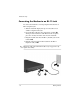
Next Steps Restoring to a Restore Point To restore the notebook to a restore point: 1. Make sure the notebook is connected to reliable external power through the AC adapter. 2. Select Start > Help and Support > System Restore. 3. Select Restore my computer to an earlier time, and then follow the instructions on the screen.
Next Steps Critical Security Updates for Windows XP Ä CAUTION: Because new computer viruses are being detected all the time, it is recommended that you install all critical updates as soon as you receive an alert from Microsoft. You should also run Windows Update on a monthly basis to install the latest recommended updates from Microsoft. A Critical Security Updates for Windows XP disc may have been included with your notebook to provide additional updates delivered after the computer was configured.
Next Steps Firewall Software When you use the notebook for e-mail, network, or Internet access, it is possible for unauthorized persons to obtain information about you, your notebook, and your data. Firewalls monitor all incoming and outgoing traffic on your computer by including features such as logging and reporting, automatic alarms, and user interfaces for configuring the firewall. To protect your privacy, it is recommended that you use firewall software.
Next Steps Use the Notebook Safely Å WARNING: To reduce the risk of electric shock or damage to your equipment: ■ Plug the power cord into an electrical outlet that is easily accessible at all times. ■ To disconnect power from the notebook, unplug the power cord from the electrical outlet. ■ If provided with a three-pin attachment plug on your power cord, plug the cord into a grounded (earthed) three-pin outlet. Do not disable the power cord grounding pin; for example, by using a 2-pin adapter.
Next Steps Turn Off the Notebook Properly Whenever possible, turn off the notebook by using the standard Windows shutdown procedure for your operating system. To turn off the notebook: » Select Start > Turn Off Computer > Turn Off. If the notebook does not respond, try the following emergency shutdown procedures in the order shown: 3–8 ■ Press ctrl+alt+delete, select Shut Down, and then select Turn Off from the drop-down list. ■ Press and hold down the power/standby button for at least 4 seconds.
Next Steps Connect to the Internet To connect the notebook to the Internet, you must enable your communication hardware and have an account with an Internet service provider (ISP). Enable Communication Hardware Your modem is enabled when the modem cable is connected to the notebook and to an analog telephone line. ■ If you connected the modem cable during hardware setup, your modem is enabled. Proceed to the following section, “Set Up Internet Service.
Next Steps Set Up Internet Service You must set up Internet service before you can connect to the Internet. Arrangements have been made with leading ISPs in many locations to help you set up a new Internet account or to configure your notebook to use an existing account. Depending on your location, you may be able to set up Internet service by using the Easy Internet Sign-up utility or an ISP-provided icon on your desktop.
Next Steps If the Easy Internet Sign-Up utility is not available, see the following sections, “Using an ISP-Provided Icon” or “Using the Internet Connection Wizard.” Using an ISP-Provided Icon If ISP-provided icons are supported in the country in which you purchased your notebook, the icons may be displayed either individually on the Windows desktop or grouped in a desktop folder named Online Services.
Next Steps Preview the Help and Support Guide The Help and Support Guide included with your notebook contains ■ Information about the interactive Help and Support utility and the Notebook Documentation CD. ■ Instructions for updating your operating system, adding or changing any settings you skipped or entered during software setup, and setting additional preferences. ■ Instructions for installing additional software. ■ Tips for quick troubleshooting.
4 Notebook Tour This chapter identifies the visible hardware features of your notebook. To find out how to use a feature, such as hotkeys, or to find out about a general topic, such as Standby or Hibernation, refer to the Hardware and Software Guide on the Notebook Documentation CD.
Notebook Tour Top Components TouchPad Component Description 1 TouchPad light On: TouchPad is enabled. 2 TouchPad* Moves the pointer and selects or activates items on the screen. 3 Left and right TouchPad buttons (2)* Function like the left and right buttons on an external mouse. 4 TouchPad left/right scroll zone* Scrolls left or right.
Notebook Tour Component Description 5 TouchPad up/down scroll zone* Scrolls up or down. 6 TouchPad button Enables/disables the TouchPad. *This table describes default settings. For information about changing the functions of TouchPad features, refer to the Hardware and Software Guide on the Notebook Documentation CD.
Notebook Tour Keys 4–4 Component Description 1 Function keys Perform system and application tasks. When combined with the fn key, the function keys perform additional tasks as hotkeys. For more information, refer to the Hardware and Software Guide on the Notebook Documentation CD. 2 fn key Combines with other keys to perform system tasks, and activates hotkeys. For example, pressing fn+f8 increases screen brightness. 3 Windows logo key Displays the Windows Start menu.
Notebook Tour Power Control Component Description Power/standby button* When the notebook is ■ Off, press to turn on the notebook. ■ On, briefly press to initiate Hibernation. ■ In Standby, briefly press to resume from Standby. ■ In Hibernation, briefly press to restore from Hibernation. the system has stopped ✎ Ifresponding and Windows shutdown procedures cannot be used, press and hold the power/standby button for at least 4 seconds to turn off the notebook. *This table describes default settings.
Notebook Tour Lights Component Description 1 Caps lock light On: Caps lock is on. 2 Num lock light On: Num lock or the numeric keypad is on. 3 Wireless light On: An integrated wireless device has been enabled (select models only).
Notebook Tour Buttons Component Description 1 Volume down button Decreases system volume. 2 Volume up button Increases system volume. 3 Volume mute button Mutes or restores system volume. 4 Wireless button Turns the wireless network device on and off (select models only).
Notebook Tour Front Components 4–8 Component Description 1 Display release button Opens the notebook. 2 Stereo speakers (2) Produce stereo sound. 3 Wireless light On: An integrated wireless device has been enabled (select models only). 4 Power/standby light On: Notebook is turned on. Blinking: Notebook is in Standby. 5 IDE (Integrated Drive Electronics) drive light On: Internal hard drive or optical drive is being accessed. 6 Battery light On: Battery pack is charging.
Notebook Tour Rear Components Connectors, Jacks and Ports Component Description 1 Power connector Connects an AC adapter. 2 USB port Connects an optional 1.1- or 2.0-compliant USB device. 3 S-Video-out jack Connects an optional S-Video device, such as a television, VCR, camcorder, projector, or video capture card. 4 External monitor port Connects an optional VGA external monitor or projector. 5 Security cable slot Attaches an optional security cable to the notebook.
Notebook Tour Vent Component Description Exhaust vent Provides airflow to cool internal components. Ä 4–10 To prevent overheating, do not obstruct vents. Do not allow a hard surface, such as a printer, or a soft surface, such as a pillow, blanket, rug, or thick clothing, to block airflow.
Notebook Tour Left-Side Components Connectors, Jacks and Components Component Description 1 USB port Connects an optional 1.1- or 2.0-compliant USB device. 2 Audio-in (microphone) jack Connects an optional monaural microphone. 3 Audio-out (headphone) jack Connects optional headphones or powered stereo speakers. Also connects the audio function of an audio/video device such as a television or VCR. 4 Optical drive* Supports an optical disc.
Notebook Tour Vent Component Description Exhaust vent Provides airflow to cool internal components. Ä 4–12 To prevent overheating, do not obstruct vents. Do not allow a hard surface, such as a printer, or a soft surface, such as a pillow, blanket, rug, or thick clothing, to block airflow.
Notebook Tour Right-Side Components Component Description 1 Digital Media Slot Supports the following optional digital cards: SD (Secure Digital) Memory Card, SD I/O Card, Memory Stick, Memory Stick Pro, MultiMediaCard, xD-Picture Card, and SmartMedia card. 2 PC Card eject button Ejects an optional PC Card from the PC Card slot. 3 PC Card slot Supports an optional Type I or Type II 32-bit (CardBus) or 16-bit PC Card. 4 ExpressCard slot Supports an optional ExpressCard.
Notebook Tour Component Description 6 Digital drive eject button Ejects an optional HP USB Digital Drive from the digital drive bay. 7 USB ports (2) Connect optional 1.1- or 2.0-compliant USB devices. 8 1394 port Connects an optional 1394 device, such as a camcorder. 9 RJ-11 (modem) jack Connects a modem cable. (Included with select models.) - RJ-45 (network) jack Connects a network cable. (A network cable is included with select models.
Notebook Tour Bottom Components Bays and Memory Compartment Component Description 1 Memory compartment Contains 2 memory slots. Depending on the model, when the notebook is shipped, either one or both memory slots are filled with a replaceable memory module. 2 Battery pack release latch Releases a battery pack from the battery bay. 3 Battery bay Holds a battery pack. 4 Hard drive bay Holds the internal hard drive.
Notebook Tour Vents Component Description Vents (8) Provide airflow to cool internal components. Ä 4–16 To prevent overheating, do not obstruct vents. Do not allow a hard surface, such as a printer, or a soft surface, such as a pillow, blanket, rug, or thick clothing, to block airflow.
Notebook Tour Additional Standard Components The components included with the notebook vary by region, country, notebook model, and the optional hardware ordered. The following sections identify the standard external accessories and components included with most notebook models.
Notebook Tour Cables and Cord Component Description 1 Connects the notebook to a telephone jack or to a country-specific modem adapter. Modem cable* (included with select models) modem cable has a 6-pin ✎ ARJ-11 telephone connector at each end. 2 Power cord* Connects the AC adapter to an AC outlet. 3 Network cable (not included) Connects the notebook to a network jack. network cable has an 8-pin ✎ ARJ-45 network connector at each end.
Notebook Tour Adapters and Battery Pack ✎ AC adapter appearance may vary. Component Description 1 AC adapter Converts AC power to DC power. 2 Country-specific modem adapter (included by region as required) Adapts the modem cable to a non-RJ-11 telephone jack. 3 Battery pack Provides power to the notebook when the notebook is not connected to external power.
Notebook Tour Labels The labels affixed to the notebook and to some notebook components provide information you may need when troubleshooting system problems or traveling internationally with the notebook. 4–20 ■ The Microsoft Certificate of Authenticity label contains the Product Key number. You may need this number to update or troubleshoot problems with the operating system. ■ The system label provides regulatory information about the notebook.
Notebook Tour Restoration and Documentation Discs Discs for repairing or reinstalling software and for obtaining supplementary information about the notebook are included with the notebook. ■ For information about restoring, repairing, or reinstalling software, refer to the Hardware and Software Guide on the Notebook Documentation CD.
Index TouchPad 2–3, 4–2 volume 4–7 wireless 4–7 See also keys; latch 1394 port 4–14 A AC adapter connecting 1–9 identifying 1–3, 4–19 antivirus software 3–2 audio-in (microphone) jack 4–11 audio-out (headphone) jack 4–11 B battery bay identifying 4–15 inserting battery pack 1–4 battery light 1–10, 4–8 battery pack charging 1–10 identifying 1–3, 4–19 inserting 1–4 battery pack release latch 4–15 buttons digital drive eject 4–14 display release 4–8 optical drive release 4–11 PC Card eject 4–13 power/standb
Index D dates 2–4 description of notebook 2–7 digital cards 4–13 digital drive bay 4–13 digital drive eject button 4–14 Digital Media Slot 4–13 display release button identifying 4–8 using 1–8 documentation 4–21 DSL connections 1–5 E Easy Internet Sign-Up utility 3–10 electric shock warning 3–7 emergency shutdown procedures 3–8 End-User License Agreement 2–5 exhaust vents left-side 4–12 rear 4–10 expansion port 2 4–14 ExpressCard slot 4–13 external monitor port 4–9 I IDE drive light 4–8 intake vents 4–16
Index K keypad 4–4 keys fn 4–4 function 4–4 keypad 4–4 Windows applications 4–4 Windows logo 4–4 See also buttons; latch 4–4 L labels Microsoft Certificate of Authenticity 4–20 modem approvals 4–20 product identification 4–20 system 4–20 wireless certification 4–20 language selection, during setup 2–2 latch battery pack release 4–15 See also buttons; keys lights battery 1–10, 4–8 caps lock 4–6 IDE drive 4–8 num lock 4–6 power/standby 4–8 TouchPad 4–2 wireless 4–6 locked system 3–8, 4–5 M Maintenance, Shi
Index Notebook Documentation CD 4–21 notebook name 2–7 num lock light 4–6 number, Product Key 4–20 O opening the notebook 1–8 operating system installing 2–1 Microsoft Certificate of Authenticity label 4–20 Product Key number 4–20 registration 2–8 optical drive release button 4–11 optical drives 4–11 P PC Card eject button 4–13 PC Card slot 4–13 ports 1394 4–14 expansion port 2 4–14 external monitor 4–9 USB 4–9, 4–11, 4–14 See also jacks power connecting 1–9 safety 3–7 power connector 1–9, 4–9 power cord
Index S Safety and Comfort Guide 4–21 safety information 3–7 SD (Secure Digital) Memory Card 4–13 SD I/O Card 4–13 security cable slot 4–9 security features 3–1 serial number 4–20 setting preferences 2–1 setting up hardware 1–1 setting up software 2–1 slots Digital Media 4–13 ExpressCard 4–13 PC Card 4–13 security cable 4–9 SmartMedia card 4–13 software restoration 4–21 software setup 2–1 speakers 4–8 Standby power/standby light 4–8 resuming from 4–5 support, user 4–21 surge protection 3–6 S-Video-out jack
Index Windows XP category view 3–1 classic view 3–1 wireless button 4–7 wireless certification labels 4–20 wireless devices, enabling 3–9 wireless light 4–6 X xD-Picture Card 4–13 Index–6 Getting Started