Hardware Reference Guide HP Compaq 8100 Elite Small Form Factor Business PC and HP Z200 Small Form Factor Workstation
© Copyright 2010 Hewlett-Packard Development Company, L.P. Microsoft, Windows, and Windows Vista are either trademarks or registered trademarks of Microsoft Corporation in the United States and/or other countries. The only warranties for HP products and services are set forth in the express warranty statements accompanying such products and services. Nothing herein should be construed as constituting an additional warranty.
About This Book This guide provides basic information for upgrading this computer model. WARNING! Text set off in this manner indicates that failure to follow directions could result in bodily harm or loss of life. CAUTION: Text set off in this manner indicates that failure to follow directions could result in damage to equipment or loss of information. NOTE: ENWW Text set off in this manner provides important supplemental information.
iv About This Book ENWW
Table of contents Hardware Upgrades ............................................................................................................................................ 1 Warnings and Cautions ........................................................................................................................ 1 Additional Information ........................................................................................................................... 1 Unlocking the Smart Cover Lock ........
Optical Drive Precautions ................................................................................................................... 51 Operation ........................................................................................................................... 51 Cleaning ............................................................................................................................. 51 Safety .....................................................................................
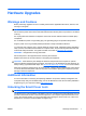
Hardware Upgrades Warnings and Cautions Before performing upgrades be sure to carefully read all of the applicable instructions, cautions, and warnings in this guide. WARNING! To reduce the risk of personal injury from electrical shock, hot surfaces, or fire: Disconnect the power cord from the wall outlet and allow the internal system components to cool before touching. Do not plug telecommunications or telephone connectors into the network interface controller (NIC) receptacles.
Smart Cover FailSafe Key If you enable the Smart Cover Lock and cannot enter your password to disable the lock, you will need a Smart Cover FailSafe Key to open the computer cover. You will need the key to access the internal computer components in any of the following circumstances: ● Power outage ● Startup failure ● PC component (for example, processor or power supply) failure ● Forgotten password NOTE: The Smart Cover FailSafe Key is a specialized tool available from HP.
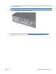
6. Use the Smart Cover FailSafe Key to remove the tamper-proof screw that secures the Smart Cover Lock to the chassis. NOTE: Your computer may look different than the illustration shown below. Figure 1 Removing the Smart Cover Lock Screw You can now remove the access panel. See Removing the Computer Access Panel on page 4. To reattach the Smart Cover Lock, secure the lock in place with the tamper-proof screw.
Removing the Computer Access Panel 1. Remove/disengage any security devices that prohibit opening the computer. 2. Remove all removable media, such as compact discs or USB flash drives, from the computer. 3. Turn off the computer properly through the operating system, then turn off any external devices. 4. Disconnect the power cord from the power outlet and disconnect any external devices.
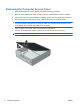
Replacing the Computer Access Panel Slide the lip on the front end of the access panel under the lip on the front of the chassis (1) then press the back end of the access panel onto the unit so that it locks into place (2). NOTE: Your computer may look different than the illustration shown below.
Removing the Front Bezel 1. Remove/disengage any security devices that prohibit opening the computer. 2. Remove all removable media, such as compact discs or USB flash drives, from the computer. 3. Turn off the computer properly through the operating system, then turn off any external devices. 4. Disconnect the power cord from the power outlet and disconnect any external devices.
2. To remove a bezel blank, push the two retaining tabs that hold the bezel blank in place towards the outer right edge of the bezel (1) and slide the bezel blank back and to the right to remove it (2). NOTE: Your computer may look different than the illustration shown below.
Replacing the Front Bezel Insert the three hooks on the bottom side of the bezel into the rectangular holes on the chassis (1) then rotate the top side of the bezel onto the chassis (2) and snap it into place. NOTE: Your computer may look different than the illustration shown below. Figure 6 Replacing the Front Bezel Using the Small Form Factor Computer in a Tower Orientation The Small Form Factor computer can be used in a tower orientation with an optional tower stand that can be purchased from HP. 1.
5. Orient the computer so that its right side is facing down and place the computer in the optional stand. NOTE: Your computer may look different than the illustration shown below. Figure 7 Changing from Desktop to Tower Orientation NOTE: To stabilize the computer in a tower orientation, HP recommends the use of the optional tower stand. 6.
NOTE: Ensure at least 10.2 centimeters (4 inches) of space on all sides of the computer remains clear and free of obstructions.
Installing Additional Memory The computer comes with double data rate 3 synchronous dynamic random access memory (DDR3SDRAM) dual inline memory modules (DIMMs). DIMMs The memory sockets on the system board can be populated with up to four industry-standard DIMMs. These memory sockets are populated with at least one preinstalled DIMM. To achieve the maximum memory support, you can populate the system board with up to 16-GB of memory.
Installing DIMMs CAUTION: You must disconnect the power cord and wait approximately 30 seconds for the power to drain before adding or removing memory modules. Regardless of the power-on state, voltage is always supplied to the memory modules as long as the computer is plugged into an active AC outlet. Adding or removing memory modules while voltage is present may cause irreparable damage to the memory modules or system board. The memory module sockets have gold-plated metal contacts.
7. Rotate up the external drive bay housing to access the memory module sockets on the system board. NOTE: Your computer may look different than the illustration shown below. Figure 9 Rotating the Drive Cage Up 8. ENWW Locate the memory modules on the system board.
9. Open both latches of the memory module socket (1), and insert the memory module into the socket (2). NOTE: Your computer may look different than the illustration shown below. Figure 10 Installing a DIMM NOTE: A memory module can be installed in only one way. Match the notch on the module with the tab on the memory socket. A DIMM must occupy the black DIMM0 socket. NOTE: Populate the DIMM sockets in the following load order: DIMM1, DIMM3, DIMM2, then DIMM4. 10.
Removing or Installing an Expansion Card The computer has one PCI expansion slot, one PCI Express x1 expansion slot, one PCI Express x16 expansion slot, and one PCI Express x16 expansion slot that is downshifted to a x4 slot. NOTE: The PCI and PCI Express slots support only low profile cards. NOTE: slot.
8. Release the slot cover retention latch that secures the PCI slot covers by lifting the green tab on the latch and rotating the latch to the open position. NOTE: Your computer may look different than the illustration shown below. Figure 11 Opening the Expansion Slot Retainer 9. Before installing an expansion card, remove the expansion slot cover or the existing expansion card. a.
b. If you are removing a standard PCI card or PCI Express x1 card, hold the card at each end, and carefully rock it back and forth until the connectors pull free from the socket. Pull the expansion card straight up from the socket (1) then away from the inside of the chassis to release it from the chassis frame (2). Be sure not to scrape the card against the other components. NOTE: Before removing an installed expansion card, disconnect any cables that may be attached to the expansion card.
c. If you are removing a PCI Express x16 card, pull the retention arm on the back of the expansion socket away from the card and carefully rock the card back and forth until the connectors pull free from the socket. Pull the expansion card straight up from the socket then away from the inside of the chassis to release it from the chassis frame. Be sure not to scrape the card against the other components. NOTE: Your computer may look different than the illustration shown below.
12. To install a new expansion card, hold the card just above the expansion socket on the system board then move the card toward the rear of the chassis (1) so that the bracket on the card is aligned with the open slot on the rear of the chassis. Press the card straight down into the expansion socket on the system board (2). NOTE: Your computer may look different than the illustration shown below.
15. Replace the access panel. 16. If the computer was on a stand, replace the stand. 17. Reconnect the power cord and turn on the computer. 18. Lock any security devices that were disengaged when the access panel was removed. 19. Reconfigure the computer, if necessary. Drive Positions NOTE: Your computer may look different than the illustration shown below. Figure 17 Drive Positions Table 1 Drive Positions 1 3.5-inch internal hard drive bay 2 3.
Installing and Removing Drives When installing additional drives, follow these guidelines: ● The primary Serial ATA (SATA) hard drive must be connected to the dark blue primary SATA connector on the system board. ● Connect a SATA optical drive to the white SATA connector on the system board. ● Connect an optional eSATA adapter cable to the black ESATA connector on the system board. ● Connect a media card reader USB cable to the media USB connector on the system board.
CAUTION: To prevent loss of work and damage to the computer or drive: If you are inserting or removing a drive, shut down the operating system properly, turn off the computer, and unplug the power cord. Do not remove a drive while the computer is on or in standby mode. Before handling a drive, ensure that you are discharged of static electricity. While handling a drive, avoid touching the connector. For more information about preventing electrostatic damage, refer to Electrostatic Discharge on page 49.
Removing an External 5.25-inch Drive CAUTION: computer. All removable media should be taken out of a drive before removing the drive from the To remove a 5.25-inch external drive: 1. Remove/disengage any security devices that prohibit opening the computer. 2. Remove all removable media, such as compact discs or USB flash drives, from the computer. 3. Turn off the computer properly through the operating system, then turn off any external devices. 4.
8. If removing an optical drive, disconnect the power cable (1) and data cable (2) from the rear of the optical drive. NOTE: Your computer may look different than the illustration shown below. Figure 20 Disconnecting the Power and Data Cables 9. Rotate the drive cage back down to its normal position. NOTE: Your computer may look different than the illustration shown below. CAUTION: Be careful not to pinch any cables or wires when rotating the drive cage down.
10. Press down on the green drive retainer button located on the left side of the drive to disengage the drive from the drive cage (1). While pressing the drive retainer button, slide the drive back until it stops, then lift it up and out of the drive cage (2). NOTE: Your computer may look different than the illustration shown below. Figure 22 Removing the 5.25-inch Drive NOTE: To replace the drive, reverse the removal procedure.
8. Install four M3 metric guide screws in the lower holes on each side of the drive. HP has provided four extra M3 metric guide screws on the front of the chassis, under the front bezel. The M3 metric guide screws are black. Refer to Installing and Removing Drives on page 21 for an illustration of the extra M3 metric guide screws location. CAUTION: Use only 5-mm long screws as guide screws. Longer screws can damage the internal components of the drive.
10. Rotate the drive cage to its upright position. NOTE: Your computer may look different than the illustration shown below. Figure 25 Rotating the Drive Cage Up 11. Connect the SATA data cable to the white system board connector. 12. Route the data cable through the cable guides. CAUTION: There are two cable guides that keep the data cable from being pinched by the drive cage when raising or lowering it. One is located on the bottom side of the drive cage.
14. Rotate the drive cage back down to its normal position. NOTE: Your computer may look different than the illustration shown below. CAUTION: Be careful not to pinch any cables or wires when rotating the drive cage down. Figure 27 Rotating the Drive Cage Down 15. Replace the access panel. 16. If the computer was on a stand, replace the stand. 17. Reconnect the power cord and turn on the computer. 18. Lock any security devices that were disengaged when the access panel was removed.
2. Disconnect the drive cables from the rear of the drive, or, if you are removing a media card reader, disconnect the USB and 1394 cables from the system board as indicated in the following illustrations. NOTE: On some models, the media card reader does not include a 1394 port or cable. NOTE: Your computer may look different than the illustration shown below.
3. Press down on the green drive retainer button located on the left side of the drive to disengage the drive from the drive cage (1). While pressing the drive retainer button, slide the drive back until it stops, then lift it up and out of the drive cage (2). NOTE: Your computer may look different than the illustration shown below. Figure 30 Removing a 3.5-inch Drive (Media Card Reader Shown) NOTE: To replace the 3.5-inch drive, reverse the removal procedure. When replacing a 3.
3. Position the guide screws on the drive into the J-slots in the drive bay. Then slide the drive toward the front of the computer until it locks into place. NOTE: Your computer may look different than the illustration shown below. Figure 31 Installing a Drive into the 3.5-inch Drive Bay (Media Card Reader Shown) 4. ENWW Connect the appropriate drive cables: a.
Removing and Replacing the Primary 3.5-inch Internal SATA Hard Drive NOTE: The system does not support Parallel ATA (PATA) hard drives. Before you remove the old hard drive, be sure to back up the data from the old hard drive so that you can transfer the data to the new hard drive. The preinstalled 3.5-inch hard drive is located under the power supply. To remove and replace the hard drive: 1. Remove/disengage any security devices that prohibit opening the computer. 2.
8. Rotate the power supply to its upright position. The hard drive is located beneath the power supply. NOTE: Your computer may look different than the illustration shown below. Figure 33 Raising the Power Supply 9. Disconnect the power cable (1) and data cable (2) from the back of the hard drive. NOTE: Your computer may look different than the illustration shown below.
10. Press down on the green release latch next to the hard drive (1). While holding the latch down, slide the drive forward until it stops, then lift the drive up and out of the bay (2). NOTE: Your computer may look different than the illustration shown below. Figure 35 Removing the Hard Drive 11. To install a hard drive, you must transfer the silver and blue isolation mounting guide screws from the old hard drive to the new hard drive.
12. Align the guide screws with the slots on the chassis drive cage, press the hard drive down into the bay, then slide it back until it stops and locks in place. NOTE: Your computer may look different than the illustration shown below. Figure 37 Installing the Hard Drive 13. Connect the power and data cables to the back of the hard drive.
Removing and Replacing a Removable 3.5-inch SATA Hard Drive Some models are equipped with a Removable SATA Hard Drive Enclosure in the 5.25-inch external drive bay. The hard drive is housed in a carrier that can be quickly and easily removed from the drive bay. To remove and replace a drive in the carrier: NOTE: Before you remove the old hard drive, be sure to back up the data from the old hard drive so that you can transfer the data to the new hard drive. 1.
3. Remove the adhesive strip that secures the thermal sensor to the top of the hard drive (1) and move the thermal sensor away from the carrier (2). NOTE: Your computer may look different than the illustration shown below. Figure 39 Removing the Thermal Sensor 4. Remove the four screws from the bottom of the hard drive carrier. NOTE: Your computer may look different than the illustration shown below.
5. Slide the hard drive back to disconnect it from the carrier then lift it up and out of the carrier. NOTE: Your computer may look different than the illustration shown below. Figure 41 Removing the Hard Drive 6. Place the new hard drive in the carrier then slide the hard drive back so that it seats in the SATA connector on the carrier's circuit board. Be sure the connector on the hard drive is pressed all the way into the connector on the carrier's circuit board.
7. Replace the four screws in the bottom of the carrier to hold the drive securely in place. NOTE: Your computer may look different than the illustration shown below. Figure 43 Replacing the Security Screws 8. Place the thermal sensor on top of the hard drive in a position that does not cover the label (1) and attach the thermal sensor to the top of the hard drive with the adhesive strip (2). NOTE: Your computer may look different than the illustration shown below.
9. Slide the cover on the carrier (1) and replace the screw on the rear of the carrier to secure the cover in place (2). NOTE: Your computer may look different than the illustration shown below. Figure 45 Replacing the Carrier Cover 10. Slide the hard drive carrier into the enclosure on the computer and lock it with the key provided. NOTE: The carrier must be locked for power to be supplied to the hard drive.
NOTE: The lifetime of the lithium battery can be extended by plugging the computer into a live AC wall socket. The lithium battery is only used when the computer is NOT connected to AC power. HP encourages customers to recycle used electronic hardware, HP original print cartridges, and rechargeable batteries. For more information about recycling programs, go to http://www.hp.com/ recycle. 1. Remove/disengage any security devices that prohibit opening the computer. 2.
b. To insert the new battery, slide one edge of the replacement battery under the holder’s lip with the positive side up. Push the other edge down until the clamp snaps over the other edge of the battery (2). Figure 47 Removing and Replacing a Coin Cell Battery (Type 2) Type 3 a. Pull back on the clip (1) that is holding the battery in place, and remove the battery (2). b. Insert the new battery and position the clip back into place.
12. Reset the date and time, your passwords, and any special system setups using Computer Setup. 13. Lock any security devices that were disengaged when the access panel was removed. Installing a Security Lock The security locks displayed below and on the following pages can be used to secure the computer. HP/Kensington MicroSaver Security Cable Lock NOTE: Your computer may look different than the illustration shown below.
Figure 50 Installing a Padlock HP Business PC Security Lock 1. Fasten the security cable by looping it around a stationary object.
2. Thread the keyboard and mouse cables through the lock. Figure 52 Threading the Keyboard and Mouse Cables 3. Screw the lock to the chassis using the screw provided. NOTE: Your computer may look different than the illustration shown below.
4. Insert the plug end of the security cable into the lock (1) and push the button in (2) to engage the lock. Use the key provided to disengage the lock. NOTE: Your computer may look different than the illustration shown below.
Front Bezel Security The front bezel can be locked in place by installing a security screw provided by HP. To install the security screw: 1. Remove/disengage any security devices that prohibit opening the computer. 2. Remove all removable media, such as compact discs or USB flash drives, from the computer. 3. Turn off the computer properly through the operating system, then turn off any external devices. 4. Disconnect the power cord from the power outlet and disconnect any external devices.
9. Install the security screw next to the middle front bezel release tab to secure the front bezel in place. NOTE: Your computer may look different than the illustration shown below. Figure 56 Installing the Front Bezel Security Screw 10. Replace the access panel. 11. If the computer was on a stand, replace the stand. 12. Reconnect the power cord and turn on the computer. 13. Lock any security devices that were disengaged when the access panel was removed.
A Electrostatic Discharge A discharge of static electricity from a finger or other conductor may damage system boards or other static-sensitive devices. This type of damage may reduce the life expectancy of the device. Preventing Electrostatic Damage To prevent electrostatic damage, observe the following precautions: ● Avoid hand contact by transporting and storing products in static-safe containers. ● Keep electrostatic-sensitive parts in their containers until they arrive at static-free workstations.
B Computer Operating Guidelines, Routine Care and Shipping Preparation Computer Operating Guidelines and Routine Care Follow these guidelines to properly set up and care for the computer and monitor: 50 ● Keep the computer away from excessive moisture, direct sunlight, and extremes of heat and cold. ● Operate the computer on a sturdy, level surface. Leave a 10.2-cm (4-inch) clearance on all vented sides of the computer and above the monitor to permit the required airflow.
Optical Drive Precautions Be sure to observe the following guidelines while operating or cleaning the optical drive. Operation ● Do not move the drive during operation. This may cause it to malfunction during reading. ● Avoid exposing the drive to sudden changes in temperature, as condensation may form inside the unit. If the temperature suddenly changes while the drive is on, wait at least one hour before you turn off the power. If you operate the unit immediately, it may malfunction while reading.
Index A access panel locking and unlocking 1 B battery replacement 40 C computer access panel removing 3 replacing 5 computer operating guidelines 50 connecting drive cables 21 D DIMMs.