
HP Designjet T2300 eMFP Printer series - Image Quality Troubleshooting Guide: English
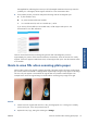
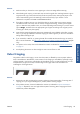

2. If the problem persists, clean and calibrate the scanner as indicated in Scanner maintenance
on page 37. Then proceed to analyze pattern number 2 of the diagnostic plot at the
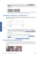
intersections between CIS modules. The example below shows a good result on the left and a bad
result on the right: the latter has light vertical banding 0.5 cm wide at the intersection between two
CIS modules.
If you see the kind of result shown on the right, call HP support and report “vertical light bands in
area fills at the intersection between CIS modules, after calibrating the scanner”.
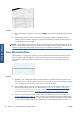
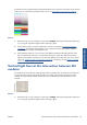
Variable line thickness or missing lines
When scanning some CAD plots at Standard resolution, mostly when working with grayscale or black-
and-white prints that contain very thin lines, you may see a variation in line thickness, or even some
missing lines, in some places:
Actions
1. Repeat the scan or copy using a higher resolution (High or Max if scanning, Normal or Best if
copying). You should also set background cleaning to 0, or set the content type to Mixed. You
might also deactivate the automatic de-skew as explained in
A copied or scanned image is very
skewed on page 36. In case you were working in black-and-white mode, we recommend using
grayscale instead.
2. If the problem persists, turn the original plot 90 degrees before scanning it again.
3. If the problem persists, clean and calibrate the scanner as indicated in
Scanner maintenance
on page 37.
4. If the problem persists, see
Defocus, blurring and fading colors on page 30.
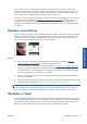
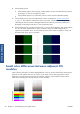
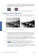
Inaccurately reproduced colors
You have to deal with several variables if you want perfect color matching between the original you
are scanning and the copy or scanned file you obtain as a result. If you find undesired colors in cases
like the example shown below (original on the left, scanned image on the right), you can follow these
guidelines.
24 Chapter 3 Troubleshooting scan-quality issues ENWW
Scan-quality issues