HP Cloud Network Manager User Guide
Document 5998-5742, edition 1 (July 2014) © Copyright 2014 Hewlett-Packard Development Company, L.P. The information contained herein is subject to change without notice. The only warranties for HP products and services are set forth in the express warranty statements accompanying such products and services. Nothing herein should be construed as constituting an additional warranty. HP shall not be liable for technical or editorial errors or omissions contained herein.
Contents Contents 3 About this guide 9 Intended audience 9 Related documents 9 Conventions 9 HP websites 9 About Cloud Network Manager Cloud Network Manager overview 10 10 Supported APs 10 Cloud Network Manager UI 10 Cloud Network Manager user interface Activating your Cloud Network Manager subscriptions Activating your HP Cloud Network Manager account User interface 11 11 12 13 Search 14 Tabs 14 Monitoring 14 Wireless configuration 14 Reports 14 Maintenance 14 Notificatio
Access points 18 AP details 18 Clients 19 WIDS 20 Event log 20 Notifications 21 Setting notification alerts Wireless configuration Initial AP configuration Importing existing configuration from AP Wireless network profiles Understanding wireless network profiles Network types 22 22 22 22 23 23 Configuring WLAN settings 23 Configuring VLAN settings for a WLAN SSID profile 26 Configuring security settings for a WLAN SSID profile 27 Configuring security settings for an employee or voice
Preventing local routing between clients 34 Enabling dynamic CPU management 34 Advanced configuration tasks 34 Customizing AP parameters 35 Configuring radio profiles for an AP 35 Configuring ARRM assigned radio profiles for an AP 35 Configuring radio profiles manually for AP 35 Configuring uplink VLAN for an AP 36 Obtaining IP address 36 Advanced radio resource management ARRM overview 37 37 Channel or power assignment 37 Voice aware scanning 37 Load aware scanning 37 Band steerin
Configuring authentication servers Configuring an external server for authentication 49 Configuring dynamic RADIUS proxy parameters 51 Configuring 802.1X authentication for a network profile 52 Configuring 802.1X authentication for a wireless network profile Configuring MAC authentication for a network profile Configuring MAC authentication for wireless network profiles 53 53 53 Configuring MAC authentication with 802.
Configuring OpenDNS credentials 68 Bonjour support configuration 68 Bonjour support overview 68 Bonjour support with Cloud Network Manager 69 Configuring Bonjour support and Bonjour support services on an AP 70 Integrating an AP with Palo Alto Networks firewall 71 Integration with Cloud Network Manager 71 Configuring an AP for PAN integration 71 Uplink configuration 72 Uplink interfaces 72 Wi-Fi uplink 72 Ethernet uplink 73 Uplink preferences and switching 74 Enforcing uplinks 74
Overview 81 Creating a report 81 Deleting a report 82 Maintenance Firmware 83 Subscription keys 83 Device management 84 User management 84 Terminology 8 | Contents 83 85 Acronyms and abbreviations 85 Glossary 86 HP Cloud Network Manager | User Guide
About this guide This user guide describes the features supported by HP Cloud Network Manager and provides detailed instructions to setup and configure the Access Point (AP). Intended audience This guide is intended for customers who configure and use Cloud Network Manager.
About Cloud Network Manager Cloud Network Manager overview HP Cloud Network Manager is a cloud-based platform that enables you to manage your HP wireless network. Designed as a software-as-a-service (SAAS) subscription, Cloud Network Manager provides a standard webbased interface that allows you to configure and monitor multiple HP wireless networks from anywhere, provided you have an internet connection. Cloud Network Manager supports APs running HP 6.4.0.2-4.1.0.0 or later versions.
Cloud Network Manager user interface The Cloud Network Manager User Interface (UI) provides a standard web-based interface that allows you to configure and monitor a Wi-Fi network.
You can add, delete, or edit the reminders by clicking a date in the calendar. You can create up to ten reminders including the initial five. 8. Read and accept the End User License agreement, and then click Finish. a. Your subscription(s) is activated in the HP Cloud Network Manager. b. You will receive a welcome email with instructions on how to create an HP Cloud Network Manager user account. If you are not a HP account administrator, forward the welcome email to the appropriate person.
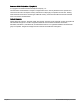
User interface The Monitoring > Overview data pane is displayed on logging into Cloud Network Manager, See Figure 1.
In addition, there are links to Support and Feedback on the right edge of the screen. Search The Search box allows administrators to search for an AP, client, or a network. When you enter text in the search box, the search function suggests matching keywords and allows you to automatically complete the search text entry. Tabs The left pane lists the Cloud Network Manager function tabs. n Monitoring n Wireless configuration n Reports n Maintenance Each tab appears in a compressed view by default.
Variables are AP parameters that can be configured, but cannot inherit values from the default group. These userdefined parameters are specific to an AP, for example, Virtual Controller (VC) name, IP address, and VLAN. Therefore, ensure that you set all parameters on all the APs in a cluster. If one or more VCs are grouped together within a cluster of APs, you can configure the APs associated with each VC as a single unit from the Cloud Network Manager.
Support You can contact HP support for troubleshooting Cloud Network Manager by clicking Support at the right edge of Cloud Network Manager. Feedback To help HP improve the Cloud Network Manager UI, click Feedback and enter your comments.
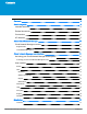
Monitoring The Monitoring tab displays the monitoring pane for Cloud Network Manager. The monitoring tab consists of: l Overview l Access points l Clients l WIDS l Event log l Notifications Overview The Overview pane displays a summary of the networks, clients, and the geographical location of the AP. Table 2: Contents of the monitoring overview pane Data pane item Description ACCESS POINTS count Displays the total number of APs.
Access points The Access Points pane displays information about the status and location of the APs. Table 3: Contents of the APs pane Data pane item Description FLAGGED AP Displays the APs that are experiencing potential issues with utilization, noise, and so on. It consists of: l ACCESS POINTS l UTIL(%) l NOISE(dBm) l ERRORS l CLIENTS l MEMORY l CPU ACCESS POINTS Displays the geographic location of the APs. It consists of: l NAME l LOCATION l STATUS l CLIENTS l IP ADDRESS l MODE l TYPE l 2.4 GHz l 5.
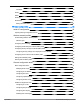
Table 4: Contents of the AP details pane Section Description DEVICE STATUS Displays the current status of the AP. CONNECTED CLIENTS Displays the number of clients that are connected to this AP. UPLINK TYPE Displays the type of uplink used. ALERTS Displays the number of alerts generated for this AP. MAP Displays the geographical location of the AP.
Data pane item Description l l l l l l l l l MAC ADDRESS IP ADDRESS USERNAME HOST NAME DEVICE TYPE ASSOC AP SSID CONNECTION LABELS THROUGHPUT graph Displays the aggregate incoming and outgoing data traffic of all clients over a specified period. DEVICE TYPE Displays the type of the device connected to the AP. Map Displays the geographic location of the clients.
Notifications The Notifications pane displays all types of notification alerts that are detected and unacknowledged by the Cloud Network Manager. Table 8: Contents of the notifications pane Data pane item Description Notifications Displays all types of notification alerts. Acknowledge All Acknowledges all the notifications in one click. Setting notification alerts To configure a notification alert: 1. At the top right edge of the main pane, click Notifications icon > Settings icon.
Wireless configuration The Wireless Configuration tab displays the configuration pane for Cloud Network Manager. This chapter provides the following information: l Initial AP configuration on page 22 l Wireless network profiles on page 22 Initial AP configuration Before connecting to Cloud Network Manager: l If an AP is shipped with factory default settings, the Cloud Network Manager applies the default configuration parameters on the AP when it connects to the Cloud Network Manager.
l Configuring WLAN settings on page 23 l Configuring VLAN settings for a WLAN SSID profile on page 26 l Configuring security settings for a WLAN SSID profile on page 27 l Configuring access rules for a WLAN SSID profile l Editing a WLAN SSID profile on page 30 l Deleting a WLAN SSID profile on page 30 Understanding wireless network profiles During start up, a wireless client searches for radio signals or beacon frames that originate from the nearest AP.
Figure 3: WLAN settings pane 2. For TYPE, select Wireless. 3. Enter a name that is used to identify the network in the Name (SSID) box. 4. Based on the type of network profile, select any of the following options under PRIMARY USAGE: l Employee l Voice l Guest 5. Click SHOW ADVANCED OPTIONS. The advanced options for configuration are displayed. Specify the following parameters as required.
Data pane item Description OPTIMIZATION quality and reliability of streaming video, while preserving the bandwidth available to the non-video clients. NOTE: When you enable DMO on multicast SSID profiles, ensure that the DMO feature is enabled on all SSIDs configured in the same VLAN. DMO CHANNEL UTILIZATION THRESHOLD Specify a value to set a threshold for DMO channel utilization.
Data pane item Description CAN BE USED WITHOUT UPLINK Select this if you do not want SSID profile to use uplink. MAX CLIENTS THRESHOLD Specify the maximum number of clients that can be configured for each BSSID on a WLAN. You can specify a value within the range of 0 to 255. The default value is 64. LOCAL PROBE REQUEST THRESHOLD Specify a threshold value to limit the number of incoming probe requests.
Configuring security settings for a WLAN SSID profile This section describes the procedure for configuring security settings for employee and voice network only. For information on guest network configuration, see Captive portal for guest access on page 56 . If you are creating a new SSID profile, configure the WLAN and VLAN settings before defining security settings. For more information, see Configuring WLAN settings on page 23 and Configuring VLAN settings for a WLAN SSID profile on page 26.
Data pane item Description l l Select an appropriate value for Tx key from Tx KEY. Enter an appropriate WEP KEY and reconfirm. 802.11r ROAMING To enable 802.11r roaming, select Enabled from 802.11r ROAMING. Selecting this enables fast BSS transition. The fast BSS transition mechanism minimizes the delay when a client transitions from one BSS to another within the same cluster. TERMINATION To terminate the EAP portion of 802.
Data pane item Description within range of 1 to 99 hours and the default value is 24 hours. MAC AUTHENTICATIO N To enable MAC address based authentication for Personal and Open security levels, set MAC AUTHENTICATION to Enabled. For Enterprise security level, the following options are available: l PERFORM MAC AUTHENTICATION BEFORE 802.1X — Select this to use 802.1X authentication only when the MAC authentication is successful. l MAC AUTHENTICATION FAIL-THRU — On selecting this, the 802.
n Create access rules for a specific user role. You can also configure an access rule to enforce Captive portal authentication for an SSID that is configured to use 802.1X authentication method. For more information, see Configuring captive portal roles for an SSID on page 63. n Create a role assignment rule. 2. Click Finish. Editing a WLAN SSID profile To edit a WLAN SSID profile: 1. In the Wireless Configuration > Networks tab, select the network that you want to edit. 2. Click Edit.
Figure 4: Configuration system tab Basic configuration tasks This section describes the following basic configuration tasks that can be performed in the System > GENERAL tab after an AP is set up: l Modifying the AP name on page 31 l Configuring VC IP address on page 32 l Configuring time zone on page 32 l Configuring a preferred band on page 32 l Configuring an NTP server on page 32 Modifying the AP name To change the name of an AP: 1. Select Wireless Configuration > System.
3. Enter the name of the AP in NAME. 4. Click Save. Configuring VC IP address You can specify a single static IP address that is used to manage a multi-AP Cloud Network Manager network. This IP address is automatically provisioned on a shadow interface on the AP that takes the role of a VC. The AP sends three Address Resolution Protocol (ARP) messages with the static IP address and its MAC address to update the network ARP cache. To configure the VC name and IP address: 1.
3. Click Save Settings.
The LED display is always in the Enabled mode during the anAP reboot. Disabling inter-user bridging If you have security and traffic management policies defined in upstream devices, you can disable bridging traffic between two clients connected to the same AP on the same VLAN. When inter-user bridging is denied, the clients can connect to the internet but cannot communicate with each other, and the bridging traffic between the clients is sent to the upstream device to make the forwarding decision.
l Configuring radio profiles for an AP on page 35 l Configuring uplink VLAN for an AP on page 36 l Obtaining IP address on page 36 Customizing AP parameters To customize the parameters of an AP: 1. Select Wireless Configuration > Access Points and click the AP you want to customize. 2. Click Edit. The edit pane for modifying AP details is displayed. 3. Under BASIC INFO, you can modify the name of the AP by entering the name in NAME. You can specify a name of up to 32 ASCII characters. 4.
When radio settings are assigned manually by the administrator, the ARRM is disabled. The following table describes various configuration modes for an AP. Table 11: AP radio modes Mode Description ACCESS In Access mode, an AP serves clients, while also monitoring for rogue APs in the background. MONITOR In Monitor mode, an AP acts as a dedicated monitor, scanning all channels for rogue APs and clients.
1. Select Wireless Configuration > Access Points and click the AP to modify. 2. Click Edit. The edit pane for modifying the AP details is displayed. 3. Under BASIC INFO, select Static to specify a static IP address. The following fields are displayed: a. Enter the new IP address for the AP in IP ADDRESS. b. Enter the subnet mask of the network in NETMASK. c. Enter the IP address of the default gateway in DEFAULT GATEWAY. d. Enter the IP address of the Domain Name System (DNS) server in DNS SERVER. e.
channels on the 5 GHz band than on the 2.4 GHz band. For more information, see Configuring ARRM on an AP on page 39. HP MotionAware The HP MotionAware feature continually monitors a RF neighborhood of the client to provide ongoing client bandsteering and load balancing, and enhanced AP reassignment for roaming mobile clients. This feature supersedes the legacy bandsteering and spectrum load balancing features, which, unlike HP MotionAware, do not trigger AP changes for clients already associated to an AP.
l Customize Valid Channels — You can customize Valid 5 GHz channels and Valid 2.4 GHz channels for 20 MHz and 40 MHz channels in the AP. The administrators can configure the ARRM channels in the channel width window. The valid channels automatically show in the static channel assignment data pane. l Minimum Transmit Power — This indicates the minimum EIRP from 3 to 33 dBm in 3 dBm increments.
Data pane item Description steers the client to the 5 GHz band (if the client is 5 GHz capable), but allows the client connection on the 2.4 GHz band if the client persistently attempts for 2.4 GHz association. Force 5 GHz Select this option to enforce 5 GHz band steering mode on the APs. Balance Bands Select this option to allow the AP to balance the clients across the two radios to best utilize the available 2.4 GHz bandwidth.
Data pane item Description for HP MotionAware. The following options are available: l l l Channel Radio Channel + Radio 5. For ACCESS POINT CONTROL, specify the following parameters: Table 15: AP control configuration parameters Data pane item Description CUSTOMIZE VALID CHANNELS Select this to customize valid channels for 2.4 GHz and 5 GHz. By default, the AP uses valid channels as defined by the Country Code (regulatory domain).
Configuring radio settings for an AP To configure 2.4 GHz and 5 GHz radio settings for an AP: 1. Select Wireless Configuration > RF > Radio. The Radio details are displayed. 2. Under 2.4.GHz, 5 GHz, or both, configure the following parameters. Table 16: Radio configuration parameters Data pane item Description LEGACY ONLY Select Enabled to run the radio in non-802.11n mode. This option is set to Disabled by default. 802.11d / 802.11h Select Enabled to allow the radio to advertise its 802.
logged information. The IDS feature in the Cloud Network Manager network enables you to detect rogue APs, interfering APs, and other devices that can potentially disrupt network operations.
You can configure the following options: l Infrastructure Detection Policies — Specifies the policy for detecting wireless attacks on APs. l Client Detection Policies — Specifies the policy for detecting wireless attacks on clients. l Infrastructure Protection Policies — Specifies the policy for protecting APs from wireless attacks. l Client Protection Policies — Specifies the policy for protecting clients from wireless attacks.
Table 18: Client detection policies Detection level Detection policy Off All detection policies are disabled.
Containment methods You can enable wired and wireless containments to prevent unauthorized stations from connecting to your Cloud Network Manager network. Cloud Network Manager supports the following types of containment mechanisms: l Wired containment — When enabled, APs generate ARP packets on the wired network to contain wireless attacks. l Wireless containment — When enabled, the system attempts to disconnect all clients that are connected or attempting to connect to the identified AP.
n MAC authentication precedes 802.1X authentication - The administrators can enable MAC authentication for 802.1X authentication. MAC authentication shares all authentication server configurations with 802.1X authentication. If a wireless or wired client connects to the network, MAC authentication is performed first. If MAC authentication fails, 802.1X authentication is not triggered. If MAC authentication is successful, 802.1X authentication is attempted. If 802.
authentication message to the AP. For more information on WISPr authentication, see Configuring WISPr authentication on page 54. Supported authentication servers Based on the security requirements, you can configure internal or external RADIUS servers.
l LEAP— Lightweight Extensible Authentication Protocol (LEAP) uses dynamic Wired Equivalent Privacy (WEP) keys for authentication between the client and authentication server. To use the internal database of an AP for user authentication, add the names and passwords of the users to be authenticated. HP does not recommend the use of LEAP authentication because it does not provide any resistance to network attacks.
Data pane item Description SHARED KEY Enter a shared key for communicating with the external RADIUS server. RETYPE SHARED KEY Re-enter the shared key. TIMEOUT Specify a timeout value in seconds. The value determines the timeout for one RADIUS request. The AP retries to send the request several times (as configured in the Retry count), before the user is disconnected. For example, if the Timeout is 5 seconds, Retry counter is 3, user is disconnected after 20 seconds. The default value is 5 seconds.
Data pane item Description ADMIN-DN Enter a distinguished name for the admin user with read/search privileges across all the entries in the LDAP database (the admin user need not have write privileges, but the admin user must be able to search the database, and read attributes of other users in the database). ADMIN PASSWORD Enter a password for the admin. RETYPE ADMIN PASSWORD Retype the password for the admin. BASE-DN Enter a distinguished name for the node that contains the entire user database.
ensure that the RADIUS traffic is routed to the required RADIUS server, enable the dynamic RADIUS proxy feature. For the AP clients to authenticate to the RADIUS servers through a different IP address and VLAN, ensure that the following steps are completed: 1. Enable dynamic RADIUS proxy. 2. Configure dynamic RADIUS proxy IP, VLAN. netmask, gateway for each authentication server. 3. Associate the authentication servers to SSID or a wired profile to which the clients connect.
4. The RADIUS server checks the user identity and authenticates the client if the user details are available in its database. The RADIUS server sends an Access-Accept message to the NAS. If the RADIUS server cannot identify the user, it stops the authentication process and sends an Access-Reject message to the NAS. The NAS forwards this message to the client and the client must re-authenticate with appropriate credentials. 5.
1. Select Wireless Configuration > Network, select an existing profile for which you want to enable MAC and 802.1X authentication and click Edit. 2. In Edit , ensure that all required WLAN and VLAN attributes are defined, and then click SECURITY tab. 3. Select SECURITY and ensure that the required parameters for MAC AUTHENTICATION and 802.1X authentication are configured. 4. Select Perform MAC authentication before 802.1X to use 802.
1. Select Wireless Configuration > System. 2. Select WISPr. The WISPr details are displayed. 3. Enter the ISO Country Code for the WISPr Location ID in the ISO COUNTRY CODE box. 4. Enter the E.164 Area Code for the WISPr Location ID in the E.164 AREA CODE box. 5. Enter the operator name of the Hotspot in the OPERATOR NAME box. 6. Enter the E.164 Country Code for the WISPr Location ID in the E.164 COUNTRY CODE box. 7. Enter the SSID/Zone section for the WISPr Location ID in the SSID/ZONE box. 8.
Session firewall based blacklisting In session firewall based blacklisting, an Access Control List (ACL) rule automates blacklisting. When the ACL rule is triggered, it sends out blacklist information and the client is blacklisted. Configuring blacklist duration To set the blacklist duration: 1. Select Wireless Configuration > Security > BLACKLISTING. 2. Under DYNAMIC BLACKLISTING: a.
Types of captive portal Cloud Network Manager supports the following types of Captive portal authentication: l l Internal Captive portal — An internal server is used for hosting the captive portal service. It supports the following types of authentication: n Internal Authenticated — When Internal Authenticated is enabled, a guest user who is pre-provisioned in the user database has to provide authentication details.
Data pane item Description MULTICAST TRANSMISSION OPTIMIZATION Select Enabled if you want the AP to select the optimal rate for sending broadcast and multicast frames based on the lowest of unicast rates across all associated clients. When this option is enabled, multicast traffic can be sent at up to 24 Mbps. The default rate for sending frames for 2.4 GHz is 1 Mbps and 5.0 GHz is 6 Mbps. This option is disabled by default.
Data pane item Description imum value is set to 60 seconds and the default value is 1000 seconds. HIDE SSID Select the if you do not want the SSID (network name) to be visible to users DISABLE SSID Select this to disable the SSID. On selecting this, the SSID is disabled, but not removed from the network. By default, all SSIDs are enabled. CAN BE USED WITHOUT UPLINK Select this if you do not want the SSID users to use uplink.
Configuring internal captive portal for guest network To configure internal captive portal authentication when adding a guest network created for wireless or wired profile: 1.
Parameter Description l l l l l l To change the color of the splash page, click the Splash page rectangle and select the required color from the BACKGROUND COLOR palette. To change the welcome text, click the first square box in the splash page, enter the required text in the WELCOME TEXT box, and click OK. Ensure that the welcome text does not exceed 127 characters. To change the policy text, click the second square in the splash page, enter the required text in the POLICY TEXT box, and click OK.
Parameter Description l l Radius Authentication - Select this option to enable user authentication against a RADIUS server. Authentication Text - Select this option to specify an authentication text. The specified text will be returned by the external server after a successful user authentication. IP or HOSTNAME Enter the IP address or the hostname of the external splash page server. URL Enter the URL of the external captive portal server.
l Role Based — Select Role Based to enable access based on user roles. For role-based access control: 1. Create a user role: a. Click New in ROLE pane. b. Enter a name for the new role and click Ok. 2. Create access rules for a specific user role: a. Click (+) icon and select appropriate options for RULE TYPE, SERVICE, ACTION, DESTINATION, and OPTIONS fields. b. Click Save. 3. Create a role assignment rule. a. Under ROLE ASSIGNMENT RULE, click New. The New Role ASSIGNMENT Rule pane is displayed. b.
Data pane item Description INTERNAL If INTERNAL is selected as splash page type: l l l l l l EXTERNAL Under SPLASH PAGE VISUALS, use the editor to specify text and colors for the initial page that will be displayed to users connecting to the network. The initial page asks for user credentials or email, depending on the splash page type configured To change the welcome text, enter the required text in WELCOME TEXT, and click Save. Ensure that the welcome text does not exceed 127 characters.
The users who do not sign up for the internet service can view the “allowed” websites (typically hotel property websites). The website names must be DNS-based and support the option to define wildcards. This works for client devices with or without HTTP proxy settings. When a user attempts to navigate to other websites, which are not in the whitelist of the walled garden profile, the user is redirected to the login page.
l Local — In this mode, the Virtual Controller acts as both the DHCP Server and default gateway. The configured subnet and the corresponding DHCP scope are independent of subnets configured in other AP clusters. The Virtual Controller assigns an IP address from a local subnet and forwards traffic to both corporate and noncorporate destinations. The network address is translated appropriately and the packet is forwarded through the IPSec tunnel or through the uplink.
Configuring DHCP server for client IP assignment The DHCP server is a built-in server, used for networks in which clients are assigned IP address by the VC. You can customize the DHCP pool subnet and address range to provide simultaneous access to more number of clients. The largest address pool supported is 2048. The default size of the IP address pool is 512.
5. Click Save Settings. Configuring OpenDNS credentials Cloud Network Manager uses the OpenDNS credentials to provide enterprise-level content filtering. To configure OpenDNS credentials: 1. Select Wireless Configuration > Services > OpenDNS. The OpenDNS details are displayed. 2. Enter the USERNAME and PASSWORD. 3. Click Save Settings.
Figure 5: Bonjour support architecture Bonjour support with Cloud Network Manager Bonjour support capabilities are available in HP WLANs where Wi-Fi data is transmitted via APs. Bonjour support is available on an HP WLAN that is managed by Cloud Network Manager. l The Bonjour support administrator assigns the Bonjour support operator role to an end user, which authorizes the user to register their device—such as an Apple TV. l Cloud Network Manager maintains information for all mDNS services.
l Bonjour support is aware of personal devices. For example, an Apple TV in a dorm room can be associated with the student who owns it. l Bonjour support is aware of shared resources.For example, an Apple TV in a meeting room or a printer in a supply room that is available to certain users, such as the marketing department. Or, in a classroom, teachers can use AirPlay to wirelessly project a laptop screen onto an HDTV monitor using an Apple TV.
5. Select required Bonjour support services. To allow all services, select ALLOWALL. 6. Based on the services configured, you can block any user roles and VLAN from accessing a Bonjour support service. The user roles and VLANs marked as disallowed are prevented from accessing the corresponding Bonjour support service. You can create a list of disallowed user roles and VLANs for all Bonjour support services configured on the AP.
6. Enter the port number within the range of 1—65535. The default port is 443. 7. Click Save Settings. Uplink configuration This section provides the following information: l Uplink interfaces on page 72 l Uplink preferences and switching on page 74 Uplink interfaces Cloud Network Manager supports Wi-Fi uplink to provide access to the corporate network. The following figure illustrates a scenario in which the APs join the VC as slave APs through a wired or mesh Wi-Fi uplink.
1. If you are configuring a Wi-Fi uplink after restoring factory settings on an AP, connect the AP to an Ethernet cable to allow the AP to get the IP address. Otherwise, go to step 2. 2. Select Wireless Configuration > System. The System details are displayed. 3. Select UPLINK and under WiFi, enter the name of the wireless network that is used for Wi-Fi uplink in the NAME (SSID) box. 4. From MANAGEMENT, select the type of key for uplink encryption and authentication.
2. Select UPLINK, perform the following steps in the PPPoE pane: a. Enter the PPPoE service name provided by your service provider in SERVICE NAME. b. In the CHAP SECRET and RETYPE CHAP SECRET fields, enter the secret key used for CHAP authentication. You can use a maximum of 34 characters for the CHAP secret key. c. Enter the user name for the PPPoE connection in the USER field. d. In the PASSWORD and RETYPE PASSWORD fields, enter a password for the PPPoE connection and confirm it. 3.
2. Under UPLINK PRIORITY LIST, select the uplink, and increase or decrease the priority. By default, the Eth0 uplink is set as a high priority uplink. 3. Click OK. The selected uplink is prioritized over other uplinks. Enabling uplink pre-emption The following configuration conditions apply to uplink pre-emption: l Pre-emption can be enabled only when no uplink is enforced.
Layer-3 (L3) mobility allows a client to roam without losing its IP address and sessions. If WLAN access parameters are the same across these networks, clients connected to APs in a given Cloud Network Manager network can roam to APs in a foreign Cloud Network Manager network and continue their existing sessions using their IP addresses. You can configure a list of Virtual Controller IP addresses across which L3 mobility is supported.
It is recommended that you configure all client subnets in the mobility domain. When client subnets are configured: l If a client is from a local subnet, it is identified as a local client. When a local client starts using the IP address, the L3 roaming is terminated. l If the client is from a foreign subnet, it is identified as a foreign client. When a foreign client starts using the IP address, the L3 roaming is set up.
l Configuring SNMP on page 78 l Configuring a syslog server on page 79 l Configuring TFTP dump server on page 80 Configuring SNMP This section provides the following information: l SNMP parameters for AP on page 78 l Configuring community string for SNMP on page 78 l Configuring SNMP traps on page 79 SNMP parameters for AP Cloud Network Manager supports SNMPv1, SNMPv2c, and SNMPv3 for reporting purposes only. An AP cannot use SNMP to set values in HP system.
1. Select Wireless Configuration > System. The System details are displayed. 2. Click the SNMP tab, and then click New under COMMUNITY STRINGS. 3. Enter the string in SNMP. 4. Click Ok. 5. To delete a community string, select the string, and click Delete. Creating community strings for SNMPv3 To create community strings for SNMPv3: 1. Select Wireless Configuration > System. The System details are displayed. 2. Click the SNMP tab. The SNMP configuration parameters are displayed. 3.
4. Select the required values to configure Syslog Facility Levels. Syslog facility is an information field associated with a syslog message. It is an application or operating system component that generates a log message. The following facilities are supported by syslog: l AP-DEBUG— Detailed log about the AP device. l NETWORK— Log about change of network, for example, when a new AP is added to a network. l SECURITY— Log about network security, for example, when a client connects using wrong password.
Reports The Reports tab displays the summary of the reports generated for networks, security, and PCI Compliance. Figure 8: Reports pane Overview The following table displays the parameters that are used to generate a report. Table 31: Contents of the reporting pane Data pane item Description TITLE Displays the title name of the report generated. DATE RUN Displays the date on which report was generated. SAVED BY Indicates the user login name using which the report was generated.
Deleting a report To delete a report: 1. Select Reports > Network or Security or PCI Compliance and then select the report that you want to delete. 2. Click Delete.
Maintenance The Maintenance tab displays the maintenance pane for the Cloud Network Manager. Figure 9: Maintenance pane The maintenance pane consists of: l Firmware l Subscription keys l Device management l User management Firmware The Firmware tab provides an overview of the latest supported version of AP, details of the AP, and the option to upgrade an AP .
Table 33: Contents of the licenses pane Data pane item Description NAME Displays the name of the license. START DATE Displays when the license is assigned to your AP. END DATE Displays the license expiry date. CAPACITY Displays the maximum capacity of the license. APs USED Displays the number of APs that use a license. Device management The Device Management tab provides details of an AP.
Terminology Acronyms and abbreviations The following table lists the abbreviations in this user guide.
Table 35: List of abbreviations Abbreviation Expansion NTP Network Time Protocol PEAP Protected Extensible Authentication Protocol PEM Privacy Enhanced Mail PoE Power over Ethernet RADIUS Remote Authentication Dial In User Service VC Virtual Controller VSA Vendor-Specific Attributes WLAN Wireless Local Area Network Glossary The following table lists the terms and their definitions in this guide. Table 36: List of terms Term Definition 802.
Table 36: List of terms Term Definition access point An access point (AP) connects users to other users within the network and also can serve as the point of interconnection between the WLAN and a fixed wire network. The number of APs a WLAN needs is determined by the number of users and the size of the network. access point mapping The act of locating and possibly exploiting connections to WLANs while driving around a city or elsewhere.
Table 36: List of terms Term Definition battery-powered. Although mobile and portable systems can be used in fixed locations, efficiency and bandwidth are compromised compared with fixed systems. frequency allocation Use of radio frequency spectrum regulated by governments. frequency spectrum Part of the electromagnetic spectrum. hotspot A WLAN node that provides internet connection from a given location.
Table 36: List of terms Term Definition wireless network In a Wireless LAN (WLAN), laptops, desktops, PDAs, and other computer peripherals are connected to each other without any network cables. These network elements or clients use radio signals to communicate with each other. Wireless networks are set up based on the IEEE 802.11 standards.