HP BladeSystem c7000 Enclosure Maintenance and Service Guide Part Number 413336-004 October 2007 (Fourth Edition)
© Copyright 2006, 2007 Hewlett-Packard Development Company, L.P. The information contained herein is subject to change without notice. The only warranties for HP products and services are set forth in the express warranty statements accompanying such products and services. Nothing herein should be construed as constituting an additional warranty. HP shall not be liable for technical or editorial errors or omissions contained herein. Microsoft and Windows are U.S.
Contents Customer self repair ...................................................................................................................... 5 Parts only warranty service ......................................................................................................................... 5 Illustrated parts catalog ............................................................................................................... 16 Mechanical components.............................................
Array Diagnostic Utility .................................................................................................................. 54 HP Instant Support Enterprise Edition................................................................................................ 54 Component identification ............................................................................................................. 56 Enclosure front components .................................................................
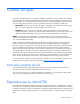
Customer self repair HP products are designed with many Customer Self Repair (CSR) parts to minimize repair time and allow for greater flexibility in performing defective parts replacement. If during the diagnosis period HP (or HP service providers or service partners) identifies that the repair can be accomplished by the use of a CSR part, HP will ship that part directly to you for replacement. There are two categories of CSR parts: • Mandatory—Parts for which customer self repair is mandatory.
• Obligatoire - Pièces pour lesquelles la réparation par le client est obligatoire. Si vous demandez à HP de remplacer ces pièces, les coûts de déplacement et main d'œuvre du service vous seront facturés. • Facultatif - Pièces pour lesquelles la réparation par le client est facultative. Ces pièces sont également conçues pour permettre au client d'effectuer lui-même la réparation.
NOTA: alcuni componenti HP non sono progettati per la riparazione da parte del cliente. Per rispettare la garanzia, HP richiede che queste parti siano sostituite da un centro di assistenza autorizzato. Tali parti sono identificate da un "No" nel Catalogo illustrato dei componenti. In base alla disponibilità e alla località geografica, le parti CSR vengono spedite con consegna entro il giorno lavorativo seguente.
anrufen und sich von einem Mitarbeiter per Telefon helfen lassen. Den Materialien, die mit einem CSRErsatzteil geliefert werden, können Sie entnehmen, ob das defekte Teil an HP zurückgeschickt werden muss. Wenn es erforderlich ist, das defekte Teil an HP zurückzuschicken, müssen Sie dies innerhalb eines vorgegebenen Zeitraums tun, in der Regel innerhalb von fünf (5) Geschäftstagen.
Centro de asistencia técnica de HP y recibirá ayuda telefónica por parte de un técnico. Con el envío de materiales para la sustitución de componentes CSR, HP especificará si los componentes defectuosos deberán devolverse a HP. En aquellos casos en los que sea necesario devolver algún componente a HP, deberá hacerlo en el periodo de tiempo especificado, normalmente cinco días laborables. Los componentes defectuosos deberán devolverse con toda la documentación relacionada y con el embalaje de envío.
periode, gewoonlijk vijf (5) werkdagen, retourneren aan HP. Het defecte onderdeel moet met de bijbehorende documentatie worden geretourneerd in het meegeleverde verpakkingsmateriaal. Als u het defecte onderdeel niet terugzendt, kan HP u voor het vervangende onderdeel kosten in rekening brengen. Bij reparatie door de klant betaalt HP alle verzendkosten voor het vervangende en geretourneerde onderdeel en kiest HP zelf welke koerier/transportonderneming hiervoor wordt gebruikt.
Para obter mais informações sobre o programa de reparo feito pelo cliente da HP, entre em contato com o fornecedor de serviços local. Para o programa norte-americano, visite o site da HP (http://www.hp.com/go/selfrepair). Serviço de garantia apenas para peças A garantia limitada da HP pode incluir um serviço de garantia apenas para peças. Segundo os termos do serviço de garantia apenas para peças, a HP fornece as peças de reposição sem cobrar nenhuma taxa.
Customer self repair 12
Customer self repair 13
Customer self repair 14
Customer self repair 15
Illustrated parts catalog Mechanical components Item Description Spare part number Customer self repair (on page 5) 1 HP BladeSystem c7000 enclosure — — 2 Rear cage — — 3 Hardware kit 432463-001 Mandatory1 a) Device bay shelf — — b) Vertical cable cover* — — Illustrated parts catalog 16
Item Description Spare part number Customer self repair (on page 5) c) Left LCD cap* — — 4 Device bay blank 414051-001 Mandatory1 5 Fan blank 414052-001 Mandatory1 6 Power supply blank 416043-001 Mandatory1 7 Onboard Administrator blank 414054-001 Mandatory1 8 Interconnect blank 414053-001 Mandatory1 9 Plastics kit* 414063-001 Mandatory1 a) Left handle cover — — b) Right handle cover — — c) Screws for endcaps and handles, rear cage (10) — — d) Rear cage endcap, top —
können bei diesem Service je nach den für Ihr Produkt vorgesehenen Garantiebedingungen zusätzliche Kosten anfallen. 3 No: Kein—Einige Teile sind nicht für Customer Self Repair ausgelegt. Um den Garantieanspruch des Kunden zu erfüllen, muss das Teil von einem HP Servicepartner ersetzt werden. Im illustrierten Teilekatalog sind diese Teile mit „No“ bzw. „Nein“ gekennzeichnet. Mandatory: Obligatorio—componentes para los que la reparación por parte del usuario es obligatoria.
Illustrated parts catalog 19
System components Front system components Item Description Spare part number Customer self repair (on page 5) 10 HP BladeSystem c7000 power supply 411099-001 Mandatory1 11 HP BladeSystem Insight Display — — 3-in Insight Display 441203-001 No3 2-in Insight Display* 415839-001 No3 Insight Display front-to-rear interconnect board 432462-001 No3 12 * Not shown 1 Mandatory—Parts for which customer self repair is mandatory.
No—Some HP parts are not designed for customer self repair. In order to satisfy the customer warranty, HP requires that an authorized service provider replace the part. These parts are identified as "No" in the Illustrated Parts Catalog. 3 Mandatory: Obligatoire—Pièces pour lesquelles la réparation par le client est obligatoire. Si vous demandez à HP de remplacer ces pièces, les coûts de déplacement et main d'œuvre du service vous seront facturés.
Optional: Opcional—Peças cujo reparo feito pelo cliente é opcional. Essas peças também são projetadas para o reparo feito pelo cliente. No entanto, se desejar que a HP as substitua, pode haver ou não a cobrança de taxa adicional, dependendo do tipo de serviço de garantia destinado ao produto. 3 No: Nenhuma—Algumas peças da HP não são projetadas para o reparo feito pelo cliente. A fim de cumprir a garantia do cliente, a HP exige que um técnico autorizado substitua a peça.
Rear system components Item Description Spare part number Customer self repair (on page 5) 13 Interconnect module (switch) — — a) HP GbE2c Ethernet Blade Switch for HP c-Class BladeSystem 414037-001 Mandatory1 b) HP GbE2c Layer 2/3 Ethernet Blade Switch for c-Class BladeSystem 438475-001 Mandatory1 c) HP 10Gb Ethernet BL-c Switch 447116-001 Mandatory1 d) HP 1:10Gb Ethernet BL-c Switch 438476-001 Mandatory1 e) Brocade 4Gb SAN Switch for HP cClass BladeSystem, 12 ports* 411120-001 Manda
Item Description Spare part number Customer self repair (on page 5) g) Brocade 4Gb SAN Switch for HP cClass BladeSystem, 24 ports with Power Pack Software* 411122-001 Mandatory1 h) Cisco Catalyst Blade Switch 3020 for HP c-Class BladeSystem* 432904-001 Mandatory1 i) HP 1/10Gb Virtual Connect Ethernet Module for c-Class BladeSystem* 399725-001 Mandatory1 j) HP 4Gb Virtual Connect Fibre Channel Module for c-Class BladeSystem* 410152-001 Mandatory1 k) HP 4X DDR IB Switch Module for HP cClass Bl
Mandatory: Obbligatorie—Parti che devono essere necessariamente riparate dal cliente. Se il cliente ne affida la riparazione ad HP, deve sostenere le spese di spedizione e di manodopera per il servizio. 2 Optional: Opzionali—Parti la cui riparazione da parte del cliente è facoltativa. Si tratta comunque di componenti progettati per questo scopo. Se tuttavia il cliente ne richiede la sostituzione ad HP, potrebbe dover sostenere spese addizionali a seconda del tipo di garanzia previsto per il prodotto.
Illustrated parts catalog 26
Removal and replacement procedures Required tools The following items are required for some procedures: • T-10 Torx screwdriver • T-15 Torx screwdriver Safety considerations Before performing service procedures, review all the safety information. Preventing electrostatic discharge To prevent damaging the system, be aware of the precautions you need to follow when setting up the system or handling parts.
WARNING: To reduce the risk of personal injury or equipment damage when unloading a rack: • At least two people are needed to safely unload the rack from the pallet. An empty 42U rack can weigh as much as 115 kg (253 lb), can stand more than 2.1 m (7 ft) tall, and may become unstable when being moved on its casters. • Never stand in front of the rack when it is rolling down the ramp from the pallet. Always handle the rack from both sides. WARNING: The enclosure is very heavy.
These symbols, on power supplies or systems, indicate that the equipment is supplied by multiple sources of power. WARNING: To reduce the risk of injury from electric shock, remove all power cords to completely disconnect power from the system. • Each enclosure has two or more power supply cords. A single rack or cabinet may contain more than one enclosure. Power may be supplied in a redundant fashion. Removing any single source of power does not necessarily remove power from any portion of the system.
• Press and release the Power On/Standby button. This method initiates a controlled shutdown of applications and the OS before the server blade enters standby mode. • Press and hold the Power On/Standby button for more than 4 seconds to force the server blade to shut down. This method forces the server blade to enter standby mode without properly exiting applications and the OS. It provides an emergency shutdown method in the event of a hung application.
3. Remove the power supply or the power supply blank. CAUTION: For best cooling practices, do not operate the enclosure for extended periods with more than one component or blank removed. When removing an active component, replace it with a blank. To replace the component, reverse the removal procedure. Device bay blank Remove the component as indicated. CAUTION: For best cooling practices, do not operate the enclosure for extended periods with more than one component or blank removed.
Device bay shelf To remove the component: 1. Remove any components in the device bays: o Device bay blank (on page 31) o Half-height or full-height blade (on page 33) 2. Slide the device bay shelf locking tab to the left to open it. 3. Push the device bay shelf back until it stops, lift the right side slightly to disengage the two tabs from the divider wall, and then rotate the right edge downward (clockwise).
4. Lift the left side of the device bay shelf to disengage the three tabs from the divider wall, and then remove it from the enclosure. To replace the component, reverse the removal procedure. Half-height or full-height blade CAUTION: This procedure provides instructions for replacement of a failed part only. To change the configuration of components, see the appropriate HP BladeSystem c-Class enclosure setup and installation guide. To remove the component: 1.
o Half-height blade o Full-height blade CAUTION: For best cooling practices, do not operate the enclosure for extended periods with more than one component or blank removed. When removing an active component, replace it with a blank. To replace the component, reverse the removal procedure. HP BladeSystem Insight Display To remove the component: 1. Power down the enclosure (on page 30). 2.
o Full-height blades: bays 1-5 ("Half-height or full-height blade" on page 33) o Device bay blanks: bays 9-13 ("Device bay blank" on page 31) o Power supplies or blanks: bays 1-4 ("HP BladeSystem c7000 power supply or power supply blank" on page 30) 3. Remove the three T-10 Torx screws that secure the Insight Display cable center cover, and then remove the cover. 4. Remove the two T-10 Torx screws that secure the Insight Display cable contour cover, and then remove the cover. 5.
9. Carefully remove the Insight Display cable through the cable channel. To replace the component, reverse the removal procedure. Fan blank To remove the component: 1. Turn the handle counterclockwise. 2. Remove the blank. CAUTION: For best cooling practices, do not operate the enclosure for extended periods with more than one component or blank removed. When removing an active component, replace it with a blank. To replace the component, reverse the removal procedure.
Active Cool fan CAUTION: This procedure provides instructions for replacement of a failed part only. To change the configuration of components, see the appropriate HP BladeSystem c-Class enclosure setup and installation guide. To remove the component: 1. Turn the handle counterclockwise. 2. Remove the fan. CAUTION: For best cooling practices, do not operate the enclosure for extended periods with more than one component or blank removed. When removing an active component, replace it with a blank.
2. Remove the blank. CAUTION: For best cooling practices, do not operate the enclosure for extended periods with more than one component or blank removed. When removing an active component, replace it with a blank. To replace the component, slide the component into the bay until it locks into place. Interconnect switch or Pass-Thru module CAUTION: This procedure provides instructions for replacement of a failed part only.
4. Remove the interconnect switch or Pass-Thru module. CAUTION: For best cooling practices, do not operate the enclosure for extended periods with more than one component or blank removed. When removing an active component, replace it with a blank. To replace the component, reverse the removal procedure. Interconnect bay dividers To remove the component: 1. Remove the interconnect switches and Pass-Thru modules ("Interconnect switch or Pass-Thru module" on page 38). 2.
4. Remove the interconnect bay divider. To replace the component, reverse the removal procedure. Onboard Administrator blank Remove the component as indicated. CAUTION: For best cooling practices, do not operate the enclosure for extended periods with more than one component or blank removed. When removing an active component, replace it with a blank. To replace the component, reverse the removal procedure.
Onboard Administrator To remove the component: 1. Disconnect all cables from the component. 2. Press the release tab and open the the handle. 3. Remove the Onboard Administrator module. CAUTION: For best cooling practices, do not operate the enclosure for extended periods with more than one component or blank removed. When removing an active component, replace it with a blank. To replace the component, reverse the removal procedure. Onboard Administrator tray To remove the component: 1.
4. Remove the Onboard Administrator tray. CAUTION: For best cooling practices, do not operate the enclosure for extended periods with more than one component or blank removed. When removing an active component, replace it with a blank. To replace the component, reverse the removal procedure. AC input module To remove the component: 1. Power down the server blades ("Power down the server blade" on page 29). 2. Power down the enclosure (on page 30). 3.
To replace the component, reverse the removal procedure. Rear cage WARNING: To reduce the risk of damage to the midplane and component connectors, always remove or disengage and extend all blades and power supplies 7.62 cm (3 in) before removing or installing the rear cage. WARNING: To reduce the risk of personal injury or equipment damage, at least two people are needed to safely move the rear cage. IMPORTANT: When removing components from the rear cage, note their position for later replacement.
b. Use the handles to extend the rear cage until the release levers engage on both sides of the rear cage. c. Grasp the handholds below the release levers. d. Disengage the release levers on both sides of the rear cage. CAUTION: When removing and lifting the rear cage, always grasp the handholds as far forward as possible. The front end of the rear cage is heavy and the handholds provide a more balanced location to distribute the weight of the cage during lifting.
e. Use the handholds to extend and remove the rear cage from the enclosure. To replace the component, reverse the removal procedure. Insight Display front-to-rear interconnect board WARNING: To reduce the risk of damage to the midplane and component connectors, always remove or disengage and extend all blades and power supplies 7.62 cm (3 in) before removing or installing the rear cage. To remove the component: 1. Power down the server blades ("Power down the server blade" on page 29). 2.
13. Remove the three T-10 Torx screws that secure the Insight Display cable center cover, and then remove the cover. 14. Remove the two T-10 Torx screws that secure the Insight Display cable contour cover, and then remove the cover. 15. Disconnect the Insight Display cable. 16. Remove the four T-15 Torx screws that secure the interconnect board cover, and then remove the cover. NOTE: The device bay walls have been removed for clarity.
17. Remove the two slotted T-15 Torx screws that secure the interconnect board. 18. Remove the interconnect board. To replace the component, reverse the removal procedure. Insight Display signal pass-thru board WARNING: To reduce the risk of damage to the midplane and component connectors, always remove or disengage and extend all blades and power supplies 7.62 cm (3 in) before removing or installing the rear cage. To remove the component: 1.
4. Disengage and extend the following components approximately 7.62 cm (3 in): o Half-height and full-height blades ("Half-height or full-height blade" on page 33) o Power supplies ("HP BladeSystem c7000 power supply or power supply blank" on page 30) o Power supply blanks ("HP BladeSystem c7000 power supply or power supply blank" on page 30) 5. Remove the fans ("Active Cool fan" on page 37). 6. Remove the fan blanks ("Fan blank" on page 36). 7.
12. Disconnect the pass-thru board from the cable. To replace the component, reverse the removal procedure. Midplane assembly WARNING: To reduce the risk of damage to the midplane and component connectors, always remove or disengage and extend all blades and power supplies 7.62 cm (3 in) before removing or installing the rear cage. To remove the component: 1. Power down the server blades ("Power down the server blade" on page 29). 2. Power down the enclosure (on page 30). 3. Disconnect all cables.
CAUTION: When removing the rear cage and midplane assembly, the connectors on the midplane assembly are susceptible to damage. Use caution to avoid damage to the pins and connectors. 10. Remove the rear cage ("Rear cage" on page 43). 11. Remove the Insight Display signal pass-thru board ("Insight Display signal pass-thru board" on page 47). WARNING: To reduce the risk of personal injury or equipment damage, at least two people are needed to safely move the rear cage. 12.
Cabling Single-phase AC configuration Three-phase AC configuration Cabling 51
Onboard Administrator cabling Item Connector Description 1 OA/iLO Onboard Administrator Ethernet connection. Use a CAT5 patch cable to connect to the management network. This is the connector for the IP address of the Onboard Administrator and for the iLO ports on each server blade. 2 USB For future USB connections. Not currently supported. 3 Serial connector Used for command line interface (CLI). Connects to a laptop or computer with a null-modem serial cable (RS232).
Diagnostic tools Troubleshooting resources NOTE: For common troubleshooting procedures, the term "server" is used to mean servers and server blades. The HP ProLiant Servers Troubleshooting Guide provides simple procedures for resolving common problems as well as a comprehensive course of action for fault isolation and identification, error message interpretation, issue resolution, and software maintenance.
HP Insight Diagnostics survey functionality HP Insight Diagnostics (on page 53) provides survey functionality that gathers critical hardware and software information on ProLiant server blades. This functionality supports operating systems that may not be supported by the server blade. For operating systems supported by the server blade, see the HP website (http://www.hp.com/go/supportos).
For more information on ISEE, refer to the HP website (http://www.hp.com/hps/hardware/hw_enterprise.html). To download HP ISEE, visit the HP website (http://www.hp.com/hps/hardware/hw_downloads.html). For installation information, refer to the HP ISEE Client Installation and Upgrade Guide (ftp://ftp.hp.com/pub/services/hardware/info/isee_client.pdf).
Component identification Enclosure front components Item Description 1 Device bays* 2 Air intake slot (Do not block.) 3 Power supply bay 1 4 Power supply bay 2 5 Power supply bay 3 6 Power supply bay 4 7 Insight Display 8 Power supply bay 5 9 Power supply bay 6 10 Air intake slot (Do not block.) *For more information, see "Device bay numbering (on page 56)." Device bay numbering Each enclosure requires interconnects to provide network access for data transfer.
IMPORTANT: When looking at the rear of the enclosure, device bay numbering is reversed.
Power supply LEDs Power LED 1 (green) Fault LED 2 (amber) Condition Off Off No AC power to the power supply On Off Normal Off On Power supply failure Power supply bay numbering Component identification 58
HP BladeSystem Insight Display Insight Display overview The Insight Display enables the rack technician to configure the enclosure initially. It also provides information about the health and operation of the enclosure. See the HP BladeSystem Onboard Administrator User Guide for additional information. The Insight Display background color varies with the condition of the enclosure health: • Blue—The Insight Display background illuminates blue when the enclosure UID is active.
HP BladeSystem Insight Display components Item Description Function 1 Insight Display screen Displays Main Menu error messages and instructions 2 Left arrow button Moves the menu or navigation bar selection left one position 3 Right arrow button Moves the menu or navigation bar selection right one position 4 OK button Accepts the highlighted selection and navigates to the selected menu 5 Down arrow button Moves the menu selection down one position 6 Up arrow button Moves the menu select
Item Description 1 Fan bay 1 2 Fan bay 2 3 Fan bay 3 4 Fan bay 4 5 Fan bay 5 6 Interconnect bay 2 7 Interconnect bay 4 8 Interconnect bay 6 9 Interconnect bay 8 10 Onboard Administrator bay 2 11 Power supply exhaust vent (do not block) 12 Fan bay 10 13 Fan bay 9 14 Fan bay 8 15 Fan bay 7 16 Fan bay 6 17 AC power connectors 18 Onboard Administrator bay 1 19 Interconnect bay 7 20 Interconnect bay 5 21 Interconnect bay 3 22 Interconnect bay 1 Interconnect module ba
Server blade signal Interconnect bay number NICs 1, 2, 3, and 4 (embedded) 1, 2 Mezzanine 1 3, 4 Mezzanine 2 5, 6 and then 7, 8 Mezzanine 3 7, 8 and then 5, 6 Interconnect bay label NOTE: For information on the location of LEDs and ports on individual interconnect modules, see the documentation that ships with the interconnect module.
Onboard Administrator LEDs and buttons Item Description 1 Onboard Administrator UID LED 2 Enclosure UID LED 3 Onboard Administrator Active LED 4 Onboard Administrator Health LED 5 Onboard Administrator reset button Fan bay numbering Component identification 63
Fan LED LED color Fan status Solid green The fan is working. Solid amber The fan has failed. Flashing amber See the Insight Display screen.
Specifications Environmental specifications Specification Value Temperature range* Operating 10°C to 35°C (50°F to 95°F) Non-operating -30°C to 60°C (-22°F to 140°F) Wet bulb temperature Operating 28ºC (82.4ºF) Non-operating 38.7ºC (101.7ºF) Relative humidity (noncondensing)** Operating 20% to 80% Non-operating 5% to 95% * All temperature ratings shown are for sea level. An altitude derating of 1°C per 304.8 m (1.8°F per 1000 ft) to 3048 m (10,000 ft) is applicable. No direct sunlight allowed.
Specification Value Maximum enclosure weight Unboxed 204.0 kg (450.0 lb) Shipping 223.6 kg (493.0 lb) * No components installed. Power specifications Single-phase power Specification Value Power cord IEC-320 C19-C20 1.22 m (4 ft) Output 2250 W per power supply Input requirements Rated input voltage 200 VAC to 240 VAC Rated input frequency 50 Hz to 60 Hz Rated input current per power supply 12.6 A at 208 VAC 11.9 A at 220 VAC 13.
Three-phase power (International) Specification Value Power cords (2) IEC-309 200/346-V to 240/415-V, 5-pin, 16-A 2.44 m (10 ft) Output 2250 W Input requirements Rated input voltage 346 VAC to 415 VAC line-to-line* 200 VAC to 240 VAC line-to-neutral 3-phase WYE Rated input frequency 50 Hz to 60 Hz Maximum input current per line 13.1 A at 200 VAC cord 11.9 A at 220 VAC 10.9 A at 240 VAC Maximum input power per line cord 7836 VA *Rated 200 VAC to 240 VAC line-to-neutral.
Acronyms and abbreviations ADU Array Diagnostics Utility CLI Command Line Interface CSR Customer Self Repair ESD electrostatic discharge I/O input/output iLO Integrated Lights-Out IML Integrated Management Log ISEE Instant Support Enterprise Edition LCD liquid crystal display LED light-emitting diode OA Onboard Administrator SAN storage area network Acronyms and abbreviations 68
SFP small form-factor pluggable SIM Systems Insight Manager SNMP Simple Network Management Protocol Acronyms and abbreviations 69
Index A AC input module 42 AC power configuration, single-phase 51 AC power configuration, three-phase 51 AC power configurations 51 ADU (Array Diagnostic Utility) 54 Array Diagnostic Utility (ADU) 54 B bay numbering, fan 60, 63 bay numbering, interconnect 60, 61 bay numbering, power supply 58 blade blank 31 buttons 56 C cable configuration 52 cables 51 cabling 51, 52 cabling, Onboard Administrator module 52 cabling, service port 52 component identification 56, 60 components 16, 54, 56 components, front p
M utilities 53 management tools 53 mechanical components 16 midplane assembly 49 W warranty 5 O Onboard Administrator 41, 53 Onboard Administrator blank 40 Onboard Administrator module, cabling 52 Onboard Administrator tray 41 overview, HP BladeSystem Insight Display 59 P part numbers 16 pass-thru module 38 power supply 30 power supply blank 30 power supply enclosure bay numbering 56 power supply LEDs 58 powering down 29, 30 R rear cage 43 rear components 23, 60 remote support and analysis tools 54 re