
Brocade Fabric OS Administrator's Guide Supporting Fabric OS v6.3.0 (53-1001336-02, November 2009)


Fabric OS Administrator’s Guide 477
53-1001336-02
Fibre Channel routing concepts
21
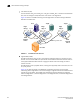
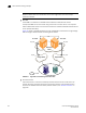
FIGURE 75 Sample topology (physical topology)
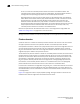
Figure 76 shows a phantom topology for the physical topology shown in Figure 75. In this figure, the
dashed lines and shapes represent the phantom topology from the perspective of Fabric 1. Fabrics
2 and 3 also see phantom topologies, but they are not shown in this example. In this figure, note
the following:
• Front domain 1 and Front domain 2 are front domains for EX_Ports connecting to Fabric 1.
There is one front domain for each FC router that is connected to Fabric 1.
• Xlate domain 1 and Xlate domain 2 represent Fabrics 2 and 3, respectively. No xlate domain is
created for Fabric 4 because there are no LSAN devices in Fabric 4.
• Target 1’, Target 2’, and Target 3’ are proxy devices for Target 1, Target 2, and Target 3,
respectively.
FIGURE 76 EX_Port phantom switch topology
Fabric 1
Fabric 2
Fabric 3
Fabric 4
Host Target 1 Target 2 Target 3
FC router 1 FC router 4FC router 3FC router 2
EX
E
EX
EX
EX
EX
EX
EX
E
E
E
E
E
E
Fabric 1
Target 1' Target 3'Target 2'
Front domain 1
(FC router 1)
Front domain 2
(FC router 2)
Xlate domain 1
(Fabric 2)
Xlate domain 2
(Fabric 3)
Host 1