
Brocade EZSwitchSetup Administrator's Guide v6.1.0 (53-1000607-02, June 2008)


EZSwitchSetup Administrator’s Guide 21
53-1000607-02
Connecting devices and completing the setup
2
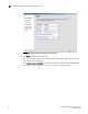
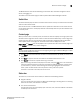
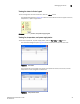
The Device Connection screen provides visual feedback as you cable the switch. A green
line indicates that the connection is correct, a red line indicates an invalid connection, and
a blue line indicates a missing connection.
.
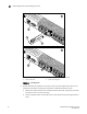
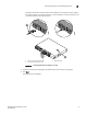
FIGURE 16 Installing Fibre Channel Cable to an SFP
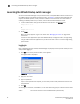
3. Verify that the connections displayed on the Device Connection screen are all green.
4. Click Next.
The Finish screen is displayed.
1 Position the Fibre Channel cable 3 Brocade switch
2 Install the Fibre Channel cable
scale: 1/8" = 1"
!
I
O
I
O
I
AT
T
E
N
T
ION
:
Ma
xi
m
um
s
cre
w
l
e
n
gt
h
f
o
r
ra
c
k
m
o
u
n
t
i
n
g
t
o
b
e5
m
m
o
r13
/
6
4i
n
.
2
1
3