
Brocade EZSwitchSetup Administrator's Guide v6.1.0 (53-1000607-02, June 2008)


EZSwitchSetup Administrator’s Guide 9
53-1000607-02
Powering up and connecting cables to the switch
2
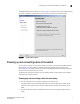
EZSwitchSetup attempts to discover or connect to the switch across the serial cable. If the
connection is successful, the Set Switch IP Address screen is displayed.
If your switch discovery fails, see Table 2 on page 15 for details on how to recover your switch.
Powering up and connecting the cable for Ethernet setup
1. Connect the power cord to the switch and plug in to a power source.
The switch power and status LEDs display amber and then change to green, which usually
takes from one to three minutes. See your switch hardware manual for the location of the
LEDs.
2. Connect an Ethernet cable from the Brocade switch to the LAN through an Ethernet hub or
switch.
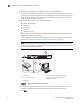
Figure 6 shows the cables connecting to the Brocade switch, setup computer, Ethernet hub or
switch, and network LAN.
NOTE
Not all switches have their Ethernet connectors in the same place as in Figure 6. Check with
your hardware documentation to determine the correct placement of the Ethernet
connections.
FIGURE 6 Cable connections for a LAN setup
3. Use the ping command to verify that your setup computer is connected to the LAN through an
Ethernet hub or switch, and that it is on the same subnet as your Brocade switch.
4. Click Next.
1 Brocade switch 5 Setup computer
2 Power cable 6 Ethernet cable going from hub or Ethernet switch to
Brocade switch
3 Ethernet hub or Ethernet switch 7 Ethernet cable going from setup computer to hub or
Ethernet switch
4 Ethernet cable from hub or switch to
LAN/WAN
!
IOIOI
0
4
3
7
1
5
2
6
8
12
11
15
9
13
10
14
1
C
3
5
2
7
6
4