
Brocade EZSwitchSetup Administrator's Guide v6.1.0 (53-1000607-02, June 2008)


8 EZSwitchSetup Administrator’s Guide
53-1000607-02
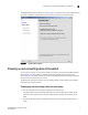
Powering up and connecting cables to the switch
2
3. Connect the serial cable from the Brocade switch to your setup computer.
A serial cable is shipped with the switch. If you cannot locate the serial cable that came with
the switch, you will need to find one that has the appropriate connectors. Some switches use a
female-to-female, DB9 connector, and other use and RJ45 connector. Do not a null-modem
cable. The serial connection settings are:
The Brocade 4900 and 5000 series uses RJ45 connectors.
• Bits per second: 9600
• Databits: 8
• Parity: none
• Stop bits: 1
• Flow control: none
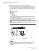
Figure 5 shows the cables connecting to the Brocade Fibre Channel switch, setup computer,
Ethernet hub or switch, and network.
If you choose to set up the switch using an Ethernet connection to your network environment,
refer to “Powering up and connecting the cable for Ethernet setup” on page 9.
NOTE
Not all switches have their serial (management console) and Ethernet connectors in the same
place as in Figure 5. Refer to the hardware documentation to determine the correct placement
of the serial and Ethernet connections.
FIGURE 5 Cable connections for a serial setup
4. Connect the setup computer to the Ethernet hub or switch. This connection will be used to
configure the Brocade switch using your Ethernet browser on your setup computer.
5. Click Next.
1 Brocade switch 5 Setup computer
2 Power cable 6 Ethernet cable from hub to Brocade switch
3 Ethernet hub or switch 7 Ethernet cable from setup computer to
Ethernet hub or switch
4Serial cable
!
IOIOI
0
4
3
7
1
5
2
6
8
12
11
15
9
13
10
14
1
C
3
5
2
4
7
6