
Brocade EZSwitchSetup Administrator's Guide v6.1.0 (53-1000607-02, June 2008)


EZSwitchSetup Administrator’s Guide 7
53-1000607-02
Powering up and connecting cables to the switch
2
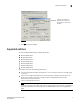
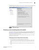
The EZSwitchSetup wizard launches, as shown in Figure 4 and gives you a choice between setting
the switch’s IP address using an Ethernet connection to your LAN or a serial connection.
FIGURE 4 EZSwitchSetup Wizard
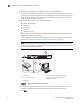
Powering up and connecting cables to the switch
The next step is to power up and connect cables to the switch, as directed by the EZSwitchSetup
wizard. Figure 5 on page 8 shows an example of cabling a Brocade switch using the serial
connection. Figure 6 on page 9 shows an example of cabling a Brocade switch using an Ethernet
connection to your LAN to setup your switch.
The Ethernet and serial port locations may vary between switch models. Refer to your hardware
documentation for exact locations.
Powering up and connecting cables for serial setup
1. Connect the power cord to the switch and plug in to a power source.
The switch power and status LEDs display amber and then change to green, which usually
takes from one to three minutes. See your switch hardware manual for the location of the
LEDs.
2. Connect an Ethernet cable from the Brocade switch to the LAN through an Ethernet hub or
switch.