HP ProLiant BL2x220c G7 Server Blade User Guide Part Number 614090-001 August 2010 (First Edition)
© Copyright 2010 Hewlett-Packard Development Company, L.P. The information contained herein is subject to change without notice. The only warranties for HP products and services are set forth in the express warranty statements accompanying such products and services. Nothing herein should be construed as constituting an additional warranty. HP shall not be liable for technical or editorial errors or omissions contained herein. Microsoft, Windows, Windows Server, and Windows NT are U.S.
Contents Component identification ............................................................................................................... 6 Front panel components ............................................................................................................................. 6 Front panel LEDs ....................................................................................................................................... 6 System board components ..................................
SmartStart Scripting Toolkit ............................................................................................................. 34 HP ROM-Based Setup Utility ............................................................................................................ 34 HP Insight Control server deployment (formerly RDP) .......................................................................... 36 Re-entering the server serial number and product ID .................................................
Regulatory compliance notices ..................................................................................................... 62 Regulatory compliance identification numbers ............................................................................................. 62 Federal Communications Commission notice ............................................................................................... 62 FCC rating label ..............................................................................
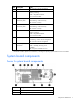
Component identification Front panel components Item Description 1 Server B Power On/Standby button 2 Server B serial label pull tab 3 Server blade release lever 4 Server A serial label pull tab 5 Server A Power On/Standby button Front panel LEDs Item Description 1 Server B system power LED Status Green = On Amber = Standby (auxiliary power available) Off = No power available to server 2 Server B UID LED Blue = Identified Blue flashing = Active remote management Component identificatio
Item Description Status Off = No active remote management 3 Server B health LED Green = Normal Flashing = Booting Amber = Degraded condition Red = Critical condition 4 Server B NIC/IB link and activity LED* Green = Network linked Green flashing = Network activity Off = No link or activity 5 Server A NIC/IB link and activity LED* Green = Network linked Green flashing = Network activity Off = No link or activity 6 Server A health LED Green = Normal Flashing = Booting Amber = Degraded condition R
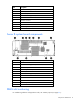
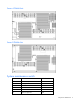
Item Description 3 Processor socket 2 (populated) 4 Server A system board serial number label 5 System battery 6 Processor socket 1 (populated) 7 Signal connector 8 Enclosure connector 9 Power connector 10 System maintenance switch 11 DIMM slots (processor 1) 12 Internal USB connector Server B system board components Item Description 1 Hard drive connector 2 Processor socket 1 (populated) 3 System battery 4 DIMM slots (processor 2) 5 Server B system board serial number labe
Server A DIMM slots Server B DIMM slots System maintenance switch Position Function Default 1 iLO 3 security override Off 2 Configuration lock Off 3 Reserved Off 4 Reserved Off 5 Password disabled Off 6 Reset configuration Off Component identification 9
Position Function Default 7 Reserved Off 8 Reserved Off When the system maintenance switch position 6 is set to the On position, the system is prepared to erase all system configuration settings from both CMOS and NVRAM. CAUTION: Clearing CMOS and/or NVRAM deletes configuration information. Be sure to properly configure the server or data loss could occur. Access components CAUTION: The jackscrews control the unseating and seating of critical system connectors.
Operations Power up the server blade The Onboard Administrator initiates an automatic power-up sequence when the server blade is installed. If the default setting is changed, use one of the following methods to power up the server blade: • Use an iLO 3 virtual power button selection for server A and server B. • Press and release the server A and server B Power On/Standby button. When the server blade goes from the standby mode to the full power mode, the system power LED changes from amber to green.
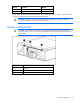
Remove the server blade To remove the component: 1. Identify the proper server blade. 2. Power down the server blade (on page 11). 3. Remove the server blade. 4. Place the server blade on a flat, level work surface. WARNING: To reduce the risk of personal injury from hot surfaces, allow the drives and the internal system components to cool before touching them. CAUTION: To prevent damage to electrical components, properly ground the server blade before beginning any installation procedure.
2. Remove the server blade (on page 12). 3. Place the server blade on a flat, level work surface with the bezel facing away from you. CAUTION: The jackscrews control the unseating and seating of critical system connectors. Failure to use the jackscrews to remove and install the server B assembly can cause the system boards to fail. 4. Turn jackscrew 1 approximately six turns counterclockwise. 5. Turn jackscrew 2 counterclockwise until the threads are fully disengaged. 6.
CAUTION: The jackscrews control the unseating and seating of critical system connectors. Failure to use the jackscrews to remove and install the server B assembly can cause the system boards to fail. 4. Engage the threads on jackscrew 1 and tighten six turns clockwise. 5. Engage the threads on jackscrew 2 and tighten fully. 6. Tighten jackscrew 1 fully.
Setup Overview To install a server blade, complete the following steps: 1. Install and configure an HP BladeSystem c-Class enclosure. 2. Install any server blade options. 3. Install interconnect modules in the enclosure. 4. Connect the interconnect modules to the network. 5. Install a server blade. 6. Complete the server blade configuration. Installing an HP BladeSystem c-Class enclosure Before performing any server blade-specific procedures, install an HP BladeSystem c-Class enclosure.
1. Remove the device bay blank. 2. Remove the enclosure connector cover. 3. Install the server blade.
Connecting to the network To connect the HP BladeSystem to a network, each enclosure must be configured with network interconnect devices to manage signals between the server blades and the external network. Two types of interconnect modules are available for HP BladeSystem c-Class enclosures: Pass-thru modules and switch modules. For more information about interconnect module options, see the HP website (http://www.hp.com/go/bladesystem/interconnects).
Server blade signal c7000 interconnect bay Server B 10G Ethernet 7 Interconnect bay labels For detailed port mapping information, see the HP BladeSystem enclosure installation poster or the HP BladeSystem enclosure setup and installation guide on the HP website (http://www.hp.com/go/bladesystem/documentation). Completing the configuration To complete the server blade and HP BladeSystem configuration, see the overview card that ships with the enclosure.
Hardware options installation Introduction If more than one option is being installed, read the installation instructions for all the hardware options and identify similar steps to streamline the installation process. WARNING: To reduce the risk of personal injury from hot surfaces, allow the drives and the internal system components to cool before touching them. CAUTION: To prevent damage to electrical components, properly ground the server before beginning any installation procedure.
o To remove the hard drive carrier from the server A assembly, remove the T-10 hard drive carrier screw and loosen the two system board thumbscrews. Then, slide the system board toward the rear of the enclosure and remove the hard drive carrier. o To remove the hard drive carrier from the server B assembly, remove the T-10 hard drive carrier screw, and then remove the hard drive carrier.
6. Prepare the hard drive carrier. 7. Install the hard drive in the carrier. 8.
o To install the hard drive assembly in server A, slide the hard drive assembly into position on the hard drive connector, slide the system board into position in the enclosure, and tighten the system board thumbscrews. Then, install the hard drive carrier retention screw. o To install the hard drive assembly in server B, first slide the hard drive assembly into position on the hard drive connector, and then install the hard drive carrier retention screw. 9. If removed, install the USB device. 10.
The memory subsystem in this server blade can support RDIMMs or UDIMMs. Both types are referred to as DIMMs when the information applies to both types. When specified as RDIMM or UDIMM, the information applies to that type only. All memory installed in the server blade must be the same type.
DIMM identification To determine DIMM characteristics, use the label attached to the DIMM and the following illustration and table. Item Description Definition 1 Size — 2 Rank 1R = Single-rank 2R = Dual-rank 4R = Quad-rank 3 Data width x4 = 4-bit x8 = 8-bit 4 Voltage rating L = Low voltage (1.
• Lockstep—provides enhanced protection while making all installed memory available to the operating system. The server blade can continue to function if a single- or multi-bit memory failure within a single DRAM device occurs. Advanced Memory Protection options are configured in RBSU. If the requested AMP mode is not supported by the installed DIMM configuration, the server blade boots in Advanced ECC mode. For more information, see "HP ROM-Based Setup Utility (on page 34).
Rank Speeds supported (MHz) Quad-rank 1066 Advanced ECC population guidelines For Advanced ECC mode configurations, observe the following guidelines: • Observe the general DIMM slot population guidelines (on page 25). • DIMMs may be installed individually. Multi-processor Advanced ECC population order For Advanced ECC mode configurations with multiple processors, populate the DIMM slots for each processor sequentially in alphabetical order (A through C).
SD card adapter option The SD card adapter option enables the use of a permanently installed SD card. WARNING: To reduce the risk of personal injury from hot surfaces, allow the drives and the internal system components to cool before touching them. To install the component: 1. Power down the server blade (on page 11). 2. Remove the server blade (on page 12). 3. Access the internal server components (on page 12). 4. Install an SD card in the SD slot. 5. Install the SD card adapter. 6.
Software and configuration utilities Server blade deployment tools HP BladeSystem c-Class Advanced management iLO 3 is a standard component of ProLiant c-Class server blades that provides server health and remote server blade manageability. Its features are accessed from a network client device using a supported web browser. In addition to other features, iLO 3 provides keyboard, mouse, and video (text and graphics) capability for a server blade, regardless of the state of the host OS or host server blade.
Deployment overview When a PXE-enabled target server blade boots, it obtains an IP address from a DHCP server. The target server blade obtains the name of the NBP from the appropriate boot server. Then, the target server blade uses TFTP to download the NBP from the boot server and executes the image. IMPORTANT: To connect to a network with a Pass-Thru module, always connect the Pass-Thru module to a network device that supports Gigabit speed.
• • o 64 MB of RAM o 64 MB of free hard drive space o 10-Mb/s network adapter PXE deployment server (storing boot images) o AMD Athlon™ XP processor (700 MHz or greater recommended), AMD Athlon™ 64 processor, or Intel® Pentium® III or higher processor (500 MHz recommended) o 256 MB of RAM o 10-Mb/s network adapter o CD-ROM drive Windows® repository server (Windows® or Linux deployment) o Windows® 2000 or Windows Server® 2003 OS installed o Network connection o CD-ROM drive o 1.
NICs can be configured to boot PXE. For more information, see "Network-based PXE deployment (on page 28)." Actual NIC numeration depends on several factors, including the OS installed on the server blade. HP recommends using one of the following methods for PXE deployment: • HP Insight Control server deployment (formerly Rapid Deployment Pack) HP Insight Control is essential server management that unlocks the management capabilities built into HP ProLiant servers.
iLO virtual CD-ROM To deploy with a boot CD: 1. Do one of the following: o Insert the boot CD into the client PC using the iLO 3 Remote Console. o Use iLO 3 to create an image file of the boot CD. o Copy the image of the boot CD to a location on the network or the client PC hard drive. 2. Remotely access the server blade through iLO 3. See "HP BladeSystem c-Class advanced management (on page 28)." 3. Click the Virtual Media tab. 4. Select the Virtual Media applet. 5.
iLO virtual floppy To deploy with a boot diskette: 1. Do one of the following: o Insert the boot diskette into the client PC using the iLO 3 Remote Console. o Use iLO 3 to create an image file of the boot diskette. o Copy the image of the boot diskette to a location on the network or the client PC hard drive. 2. Remotely access the server blade through iLO 3. See "HP BladeSystem c-Class advanced management (on page 28)." 3. Open Integrated Remote Console or Java Remote Console. 4.
SmartStart Scripting Toolkit The SmartStart Scripting Toolkit is a server deployment product that allows you to build an unattended automated installation for high-volume server blade deployments. The SmartStart Scripting Toolkit is designed to support ProLiant BL, ML, DL, and SL servers. The toolkit includes a modular set of utilities and important documentation that describes how to apply these tools to build an automated server deployment process.
Auto-configuration process The auto-configuration process automatically runs when you boot the server for the first time. During the power-up sequence, the system ROM automatically configures the entire system without needing any intervention. During this process, the ORCA utility, in most cases, automatically configures the array to a default setting based on the number of drives connected to the server. NOTE: The server may not support all the following examples.
Configuring AMP modes Not all ProLiant servers support all AMP modes. RBSU provides menu options only for the modes supported by the server. Advanced memory protection within RBSU enables the following advanced memory. • Advanced ECC Mode—Provides memory protection beyond Standard ECC. All single-bit failures and some multi-bit failures can be corrected without resulting in system downtime. • Online Spare Mode—Provides protection against failing or degraded DIMMs.
should only be used by qualified service personnel. This value should always match the serial number sticker located on the chassis. 4. Press the Enter key to clear the warning. 5. Enter the serial number and press the Enter key. 6. Select Product ID. 7. Enter the product ID and press the Enter key. 8. Press the Esc key to close the menu. 9. Press the Esc key to exit RBSU. 10. Press the F10 key to confirm exiting RBSU. The server will automatically reboot.
In addition to remote management features, iLO 3 is also responsible for managing the health of the ProLiant server. The intelligence of iLO 3 manages the Sea of Sensors thermal control, directs the Dynamic Power Capping technology, and monitors the health of server components. The iLO 3 subsystem provides secure remote access from any authorized network client.
IMPORTANT: You must install and use HP SIM to benefit from the Pre-Failure Warranty for processors, SAS and SATA hard drives, and memory modules. For additional information, refer to the Management CD in the HP ProLiant Essentials Foundation Pack or the HP SIM website (http://www.hp.com/go/hpsim). Management Agents Management Agents provide the information to enable fault, performance, and configuration management.
• Reducing the risk of security threats by automating the acquisition, scheduling the deployment, and ensuring that the patches remain in place continuously enforcing the persistence (desired state) of patches. The Vulnerability and Patch Management Pack and HP SIM can be installed on a single server (referred to as a shared configuration) or on a separate server (referred to as a distributed configuration).
consistently. Once installed, Insight Control Environment suites deliver enhanced infrastructure stability by improving control over IT assets, increasing responsiveness to business needs through flexible deployment and optimization of compute resources, and providing tangible savings through improved IT staff efficiency.
USB support and functionality USB support HP provides both standard USB 2.0 support and legacy USB 2.0 support. Standard support is provided by the OS through the appropriate USB device drivers. Before the OS loads, HP provides support for USB devices through legacy USB support, which is enabled by default in the system ROM. Legacy USB support provides USB functionality in environments where USB support is not available normally.
Survey functionality is installed with every SmartStart-assisted HP Insight Diagnostics installation, or it can be installed through the HP PSP ("ProLiant Support Packs" on page 44). NOTE: The current version of SmartStart provides the memory spare part numbers for the server blade. To download the latest version, see the HP website (http://www.hp.com/support). Integrated Management Log The IML records hundreds of events and stores them in an easy-to-view form.
Insight Manager. A dedicated server is recommended to host both HP Systems Insight Manager and HP Insight Remote Support Advanced. Details for both versions are available on the HP website (http://www.hp.com/go/insightremotesupport). To download the software for free, go to Software Depot (http://www.software.hp.com). Select Insight Remote Support from the menu on the right.
• Automatically checks for hardware, firmware, and operating system dependencies, and installs only the correct ROM upgrades required by each target server For more information, see the HP Smart Update Manager User Guide. The guide and the HP Smart Update Manager utility are available from the ProLiant Firmware Maintenance CD. This CD and others can be downloaded free of charge from the SmartStart download page on the HP website (http://www.hp.com/go/support).
Troubleshooting Troubleshooting resources The HP ProLiant Servers Troubleshooting Guide provides procedures for resolving common problems and comprehensive courses of action for fault isolation and identification, error message interpretation, issue resolution, and software maintenance on ProLiant servers and server blades. This guide includes problemspecific flowcharts to help you navigate complex troubleshooting processes. To view the guide, select a language: • English (http://www.hp.
Important safety information Before servicing this product, read the Important Safety Information document provided with the server. Symbols on equipment The following symbols may be placed on equipment to indicate the presence of potentially hazardous conditions. This symbol indicates the presence of hazardous energy circuits or electric shock hazards. Refer all servicing to qualified personnel. WARNING: To reduce the risk of injury from electric shock hazards, do not open this enclosure.
WARNING: To reduce the risk of personal injury or damage to the equipment, be sure that: • The leveling feet are extended to the floor. • The full weight of the rack rests on the leveling feet. • The stabilizing feet are attached to the rack if it is a single-rack installation. • The racks are coupled together in multiple-rack installations. • Only one component is extended at a time. A rack may become unstable if more than one component is extended for any reason.
o HP recommends you have access to the server documentation for server-specific information. o HP recommends you have access to the SmartStart CD for value-added software and drivers required during the troubleshooting process. Download the current version of SmartStart from the HP website (http://www.hp.com/servers/smartstart). Service notifications To view the latest service notifications, refer to the HP website (http://www.hp.com/go/bizsupport).
Start diagnosis flowchart Use the following flowchart to start the diagnostic process.
General diagnosis flowchart The General diagnosis flowchart provides a generic approach to troubleshooting. If you are unsure of the problem, or if the other flowcharts do not fix the problem, use the following flowchart. Item See 1 "Symptom information (on page 48)" 2 "Loose connections (on page 49)" 3 "Service notifications (on page 49)" 4 The most recent version of a particular server blade or option firmware is available on the HP Support website (http://www.hp.com/support).
Server blade power-on problems flowchart Symptoms: • The server does not power on. • The system power LED is off or amber.
• The health LED is red or amber. NOTE: For the location of server LEDs and information on their statuses, refer to the server documentation.
POST problems flowchart Symptoms: • Server does not complete POST NOTE: The server has completed POST when the system attempts to access the boot device.
Item Refer to 1 Server blade power-on problems flowchart (on page 52) 2 "POST error messages and beep codes (on page 60)" 3 "Video problems" in the HP ProLiant Servers Troubleshooting Guide located on the Documentation CD or on the HP website (http://www.hp.com/support) 4 "Symptom information (on page 48)" 5 "General memory problems are occurring" in the HP ProLiant Servers Troubleshooting Guide located on the Documentation CD or on the HP website (http://www.hp.
OS boot problems flowchart There are two ways to use SmartStart when diagnosing OS boot problems on a server blade: • Use iLO to attach virtual devices remotely to mount the SmartStart CD on the server blade. • Use an HP c-Class Blade SUV Cable and drive to connect to the server blade, and then restart the server blade.
• Server does not boot SmartStart Possible causes: • Corrupted OS • Hard drive subsystem problem • Incorrect boot order setting in RBSU Item See 1 HP ROM-Based Setup Utility User Guide (http://www.hp.com/servers/smartstart) 2 "POST problems flowchart (on page 54)" 3 • "Hard drive problems" in the HP ProLiant Servers Troubleshooting Guide located on the Documentation CD or on the HP website (http://www.hp.
* See the server blade OS boot problems flowchart (on page 56) Server fault indications flowchart Symptoms: • Server boots, but a fault event is reported by Insight Management Agents (on page 39) • Server boots, but the internal health LED, external health LED, or component health LED is red or amber Troubleshooting 58
NOTE: For the location of server LEDs and information on their statuses, refer to the server documentation. Possible causes: • Improperly seated or faulty internal or external component • Unsupported component installed • Redundancy failure • System overtemperature condition Item See 1 "Management agents (on page 39)" or in the HP ProLiant Servers Troubleshooting Guide located on the Documentation CD or on the HP website (http://www.hp.
POST error messages and beep codes For a complete listing of error messages, refer to the "POST error messages" in the HP ProLiant Servers Troubleshooting Guide located on the Documentation CD or on the HP website (http://www.hp.com/support). WARNING: To avoid potential problems, ALWAYS read the warnings and cautionary information in the server documentation before removing, replacing, reseating, or modifying system components.
Battery replacement HP recommends replacing the battery on both server A and server B when either battery is replaced. If the server blade no longer automatically displays the correct date and time, you may need to replace the battery that provides power to the real-time clock. Under normal use, battery life is 5 to 10 years. WARNING: The computer contains an internal lithium manganese dioxide, a vanadium pentoxide, or an alkaline battery pack.
Regulatory compliance notices Regulatory compliance identification numbers For the purpose of regulatory compliance certifications and identification, this product has been assigned a unique regulatory model number. The regulatory model number can be found on the product nameplate label, along with all required approval markings and information. When requesting compliance information for this product, always refer to this regulatory model number.
to radio communications. However, there is no guarantee that interference will not occur in a particular installation. If this equipment does cause harmful interference to radio or television reception, which can be determined by turning the equipment off and on, the user is encouraged to try to correct the interference by one or more of the following measures: • Reorient or relocate the receiving antenna. • Increase the separation between the equipment and receiver.
Canadian notice (Avis Canadien) Class A equipment This Class A digital apparatus meets all requirements of the Canadian Interference-Causing Equipment Regulations. Cet appareil numérique de la classe A respecte toutes les exigences du Règlement sur le matériel brouilleur du Canada. Class B equipment This Class B digital apparatus meets all requirements of the Canadian Interference-Causing Equipment Regulations.
Disposal of waste equipment by users in private households in the European Union This symbol on the product or on its packaging indicates that this product must not be disposed of with your other household waste. Instead, it is your responsibility to dispose of your waste equipment by handing it over to a designated collection point for the recycling of waste electrical and electronic equipment.
Chinese notice Class A equipment Korean notice Class A equipment Class B equipment Laser compliance This product may be provided with an optical storage device (that is, CD or DVD drive) and/or fiber optic transceiver. Each of these devices contains a laser that is classified as a Class 1 Laser Product in accordance with US FDA regulations and the IEC 60825-1. The product does not emit hazardous laser radiation. Each laser product complies with 21 CFR 1040.10 and 1040.
WARNING: The computer contains an internal lithium manganese dioxide, a vanadium pentoxide, or an alkaline battery pack. A risk of fire and burns exists if the battery pack is not properly handled. To reduce the risk of personal injury: • Do not attempt to recharge the battery. • Do not expose the battery to temperatures higher than 60°C (140°F). • Do not disassemble, crush, puncture, short external contacts, or dispose of in fire or water.
Electrostatic discharge Preventing electrostatic discharge To prevent damaging the system, be aware of the precautions you need to follow when setting up the system or handling parts. A discharge of static electricity from a finger or other conductor may damage system boards or other static-sensitive devices. This type of damage may reduce the life expectancy of the device. To prevent electrostatic damage: • Avoid hand contact by transporting and storing products in static-safe containers.
Specifications Environmental specifications Specification Value — Temperature range* Operating 10°C to 35°C (50°F to 95°F) Non-operating -30°C to 60°C (-22°F to 140°F) Relative humidity (noncondensing)** — Operating 10% to 90% @ 28°C (82.4°F) Non-operating 5% to 95% @ 38.7°C (101.7°F) Altitude† — Operating 3050 m (10,000 ft) Non-operating 9144 m (30,000 ft) * The following temperature conditions and limitations apply: - All temperature ratings shown are for sea level.
Technical support Before you contact HP Be sure to have the following information available before you call HP: • Technical support registration number (if applicable) • Product serial number • Product model name and number • Product identification number • Applicable error messages • Add-on boards or hardware • Third-party hardware or software • Operating system type and revision level HP contact information For the name of the nearest HP authorized reseller: • See the Contact HP worldwi
• Optional—Parts for which customer self repair is optional. These parts are also designed for customer self repair. If, however, you require that HP replace them for you, there may or may not be additional charges, depending on the type of warranty service designated for your product. NOTE: Some HP parts are not designed for customer self repair. In order to satisfy the customer warranty, HP requires that an authorized service provider replace the part.
Pour plus d'informations sur le programme CSR de HP, contactez votre Mainteneur Agrée local. Pour plus d'informations sur ce programme en Amérique du Nord, consultez le site Web HP (http://www.hp.com/go/selfrepair). Riparazione da parte del cliente Per abbreviare i tempi di riparazione e garantire una maggiore flessibilità nella sostituzione di parti difettose, i prodotti HP sono realizzati con numerosi componenti che possono essere riparati direttamente dal cliente (CSR, Customer Self Repair).
HINWEIS: Einige Teile sind nicht für Customer Self Repair ausgelegt. Um den Garantieanspruch des Kunden zu erfüllen, muss das Teil von einem HP Servicepartner ersetzt werden. Im illustrierten Teilekatalog sind diese Teile mit „No“ bzw. „Nein“ gekennzeichnet. CSR-Teile werden abhängig von der Verfügbarkeit und vom Lieferziel am folgenden Geschäftstag geliefert. Für bestimmte Standorte ist eine Lieferung am selben Tag oder innerhalb von vier Stunden gegen einen Aufpreis verfügbar.
el caso de todas sustituciones que lleve a cabo el cliente, HP se hará cargo de todos los gastos de envío y devolución de componentes y escogerá la empresa de transporte que se utilice para dicho servicio. Para obtener más información acerca del programa de Reparaciones del propio cliente de HP, póngase en contacto con su proveedor de servicios local. Si está interesado en el programa para Norteamérica, visite la página web de HP siguiente (http://www.hp.com/go/selfrepair).
Opcional – Peças cujo reparo feito pelo cliente é opcional. Essas peças também são projetadas para o reparo feito pelo cliente. No entanto, se desejar que a HP as substitua, pode haver ou não a cobrança de taxa adicional, dependendo do tipo de serviço de garantia destinado ao produto. OBSERVAÇÃO: Algumas peças da HP não são projetadas para o reparo feito pelo cliente. A fim de cumprir a garantia do cliente, a HP exige que um técnico autorizado substitua a peça.
Technical support 76
Technical support 77
Acronyms and abbreviations CSR Customer Self Repair DHCP Dynamic Host Configuration Protocol IB InfiniBand iLO 3 Integrated Lights-Out 3 IML Integrated Management Log NBP Network Bootstrap Program ORCA Option ROM Configuration for Arrays POST Power-On Self Test PXE Preboot Execution Environment RBSU ROM-Based Setup Utility SAS serial attached SCSI SATA serial ATA Acronyms and abbreviations 78
SIM Systems Insight Manager UID unit identification USB universal serial bus Acronyms and abbreviations 79
Index A access components 10 accessing internal components 12 Advanced ECC memory 25, 26, 36 ASR (Automatic Server Recovery) 37 auto-configuration process 35 Automatic Server Recovery (ASR) 37 B battery 66 battery replacement notice 66 beep codes 60 BIOS Serial Console 35 BIOS upgrade 37 boot options 35 BSMI notice 65 buttons 6 C cables 49, 63 Canadian notice 63 Care Pack 45 CD-ROM deployment 31 Change Control 45 Chinese notice 65 components, identification 6 configuration of system 18, 28, 33 configurati
HP Insight Server Migration Pack software for ProLiant 40 HP ProLiant Essentials Foundation Pack 38 HP ProLiant Essentials Performance Management Pack 40 HP ProLiant Essentials Rapid Deployment Pack 36 HP ProLiant Essentials Virtualization Management Software 39 HP ProLiant Essentials Vulnerability and Patch Management Pack 39 HP Smart Update Manager overview 44 HP Systems Insight Manager overview 38 HP technical support 70 I identification number 62 iLO 3 (Integrated Lights-Out 3) 28, 37 IML (Integrated M
SD card module 27 serial number 36 series number 62 server B assembly, installing 13 server B assembly, removing 12 server blade options, installing 15, 19 server blade release lever 6, 12 server blades, installing 15 server fault indications flowchart 58 server features and options 19 service notifications 49 SmartStart autorun menu 33 SmartStart Scripting Toolkit 34 SmartStart, overview 33 specifications 69 specifications, environmental 69 specifications, server 69 start diagnosis flowchart 50 static elec