
Technical data


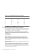

Table C–1 RF31T/RF35/RF36 DSSI ID Jumper Combinations
DSSI ID Pin 5 Pin 3 Pin 1
0 Out Out Out
1 Out Out In
2 Out In Out
3 Out In In
4 In Out Out
5 In Out In
6 InInOut
7 InInIn
C.2 How VMS Uses the DSSI Device Parameters
This section describes how the operating system uses the parameters to form
unique identifiers for each device. Configurations that require you to assign
new unit numbers for devices are also described.
With an allocation class of zero, the operating system can use the default
parameter values to provide each device with a unique device name. The
operating system uses the node name along with the device logical name in the
following manner.
NODENAME$DIAu
where NODENAME is a unique node name, and u is the unit number.
With a nonzero allocation class, the operating system relies on unit number
values to create a unique device name. The operating system uses the
allocation class along with the device logical name in the following manner.
$ALLCLASS$DIAu
where ALLCLASS is the allocation class for the system and devices, and u is a
unique unit number.
Figure C–2 illustrates the need to program unit numbers for a system using
more than one DSSI bus and a nonzero allocation class. In the case of the
nonzero allocation class, the operating system sees three of the integrated
storage elements (ISEs) as having duplicate device names, which is an error,
as all unit numbers must be unique.
C–4 Programming Parameters for DSSI Devices