
Installation Manual
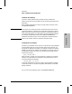


Interpreting Back-Panel LEDs
LAN port with AUI
and BNC connectors
Console port
WAN (synchronous) port
Router status LEDs
Port status
LEDs
Reset and Clear
buttons
Fan outlet
Power
Figure 2-3. Example of the Back Panel of a Single-Height Router
27290A R outerBR
Net Fai l
Wrap
Sig De t
Rx
Ring O P
Thru
Tx
See Ma nual
Pwr
Reset
Self-test
Fault
Clear
~ LI NE 5 0/60 H Z
100-120 VAC . 1. 00 A
200-240 VAC . 0. 60 A
Console Po rt
RS-2 32
BNC AUI
Rx
Tx
Net Fai l
Enabled
Ethernet/802.3 Po rt 1
BNC AUI
Rx
Tx
Net Fai l
Enabled
Ethernet/802.3 Po rt 2
BNC AUI
Rx
Tx
Net Fai l
Enabled
Ethernet/802.3 Po rt 3
BNC AUI
Rx
Tx
Net Fai l
Enabled
Ethernet/802.3 Po rt 4
A
SO POPI
Enabled
Assembly No . 27 290-60001
SI
MIC Por ts
MIC A
Optical By pass
MIC B
B
FDDI Por t
LAN port with AUI and
BNC connectors
FDDI port connectors
and status LEDs
Router status
LEDs
Reset and
clear buttons
Fan outlets
Power
LAN port
status LEDs
Console port
Figure 2-4. Example of the Back Panel of a Double-Height Router
Router Operation
Interpreting Back-Panel LEDs
2-6