
Installation Manual

A-15
Cable Specifications
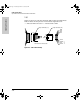
Synchronous Serial Cable Assemblies and Pinouts
Cable Specifications
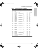
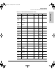
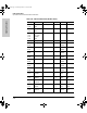
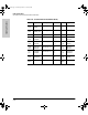
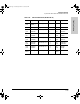
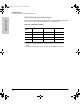
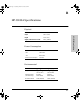
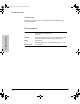
Table A-9. V.35 DTE Cable Pinouts (DB-60 to 34-Pin)
60 Pin Signal Description Direction 34 Pin Signal
J1-49
J1-48
MODE_1
GND
Shorting group – – –
J1-50
J1-51
J1-52
MODE_0
GND
MODE_DCE
Shorting group – – –
J1-53
J1-54
J1-55
J1-56
TxC/NIL
RxC_TxCE
RxD/TxD
GND
Shorting group – – –
J1-46 Shield_GND Single – J2-A Frame GND
J1-45
Shield
Circuit_GND
–
Twisted pair no. 12 –
–
J2-B
Shield
Circuit GND
–
J1-42
Shield
RTS/CTS
–
Twisted pair no. 9 —>
–
J2-C
Shield
RTS
–
J1-35
Shield
CTS/RTS
–
Twisted pair no. 8 <—
–
J2-D
Shield
CTS
–
J1-34
Shield
DSR/DTR
–
Twisted pair no. 7 <—
–
J2-E
Shield
DSR
–
J1-33
Shield
DCD/LL
–
Twisted pair no. 6 <—
–
J2-F
Shield
RLSD
–
J1-43
Shield
DTR/DSR
–
Twisted pair no. 10 —>
–
J2-H
Shield
DTR
–
J1-44
Shield
LL/DCD
–
Twisted pair no. 11 —>
–
J2-K
Shield
LT
–
J1-18
J1-17
TxD/RxD+
TxD/RxD–
Twisted pair no. 1 —>
—>
J2-P
J2-S
SD+
SD–
J1-28
J1-27
RxD/TxD+
RxD/TxD–
Twisted pair no. 5 <—
<—
J2-R
J2-T
RD+
RD–
J1-20
J1-19
TxCE/TxC+
TxCE/TxC–
Twisted pair no. 2 —>
—>
J2-U
J2-W
SCTE+
SCTE–
J1-26
J1-25
RxC/TxCE+
RxC/TxCE–
Twisted pair no. 4 <—
<—
J2-V
J2-X
SCR+
SCR–
J1-24
J1-23
TxC/RxC+
TxC/RxC–
Twisted pair no. 3 <—
<—
J2-Y
J2-AA
SCT+
SCT–
J3138.bk Page 15 Wednesday, March 18, 1998 6:07 PM