
Installation Manual

A-14
Cable Specifications
Synchronous Serial Cable Assemblies and Pinouts
Cable Specifications
V.35
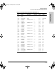
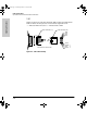
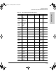
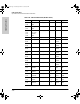
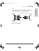
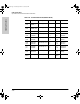
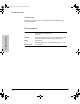
Figure A-6 shows the V.35 cable assembly. Table A-9 lists the DTE pinouts.
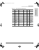
Table A-10 lists the DCE pinouts. Arrows indicate signal direction:
—> indicates DTE to DCE, and <— indicates DCE to DTE.
Figure A-6. V.35 Cable Assembly
H1975
Connectors are not to scale
60-pin connector (J1)
15-pin connector (J2)
J2-B
J2-D
J2-A
J2-C
J2-KK
J2-MM
J2-LL
J2-NN
J3138.bk Page 14 Wednesday, March 18, 1998 6:07 PM