
Installation Manual


A-12
Cable Specifications
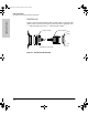
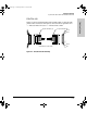
Synchronous Serial Cable Assemblies and Pinouts
Cable Specifications
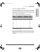
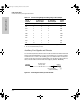
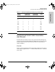
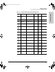
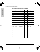
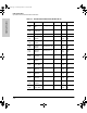
Table A-7. EIA/TIA-449 DTE Cable Pinouts (DB-60 to DB-37)
60 Pin Signal Description Direction 37 Pin Signal
J1-49
J1-48
MODE_1
GND
Shorting group – – –
J1-51
J1-52
GND
MODE_DCE
Shorting group – – –
J1-46 Shield_GND Single _ J2-1 Shield GND
J1-11
J1-12
TxD/RxD+
TxD/RxD–
Twisted pair no. 6 —>
—>
J2-4
J2-22
SD+
SD–
J1-24
J1-23
TxC/RxC+
TxC/RxC–
Twisted pair no. 9 <—
<—
J2-5
J2-23
ST+
ST–
J1-28
J1-27
RxD/TxD+
RxD/TxD–
Twisted pair no. 11 <—
<—
J2-6
J2-24
RD+
RD–
J1-9
J1-10
RTS/CTS+
RTS/CTS–
Twisted pair no. 5 —>
—>
J2-7
J2-25
RS+
RS–
J1-26
J1-25
RxC/TxCE+
RxC/TxCE–
Twisted pair no. 10 <—
<—
J2-8
J2-26
RT+
RT–
J1-1
J1-2
CTS/RTS+
CTS/RTS–
Twisted pair no. 1 <—
<—
J2-9
J2-27
CS+
CS–
J1-44
J1-45
LL/DCD
Circuit_GND
Twisted pair no. 12 —>
_
J2-10
J2-37
LL
SC
J1-3
J1-4
DSR/DTR+
DSR/DTR–
Twisted pair no. 2 <—
<—
J2-11
J2-29
DM+
DM–
J1-7
J1-8
DTR/DSR+
DTR/DSR–
Twisted pair no. 4 —>
—>
J2-12
J2-30
TR+
TR–
J1-5
J1-6
DCD/DCD+
DCD/DCD–
Twisted pair no. 3 <—
<—
J2-13
J2-31
RR+
RR–
J1-13
J1-14
TxCE/TxC+
TxCE/TxC–
Twisted pair no. 7 —>
—>
J2-17
J2-35
TT+
TT–
J1-15
J1-16
Circuit_GND
Circuit_GND
Twisted pair no. 9 –
–
J2-19
J2-20
SG
RC
J3138.bk Page 12 Wednesday, March 18, 1998 6:07 PM