
Installation Manual


A-5
Cable Specifications
Synchronous Serial Cable Assemblies and Pinouts
Cable Specifications
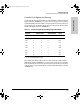
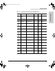
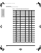
Table A-3. Auxiliary Port Signaling and Cabling Using a DB-25 Adapter
Synchronous Serial Cable Assemblies
and Pinouts
The illustrations and tables in this section provide assembly drawings and
pinouts for the EIA-530 DTE, EIA/TIA-232, EIA/TIA-449, V.35, and X.21 DTE
and DCE cables, which are used with the synchronous serial WAN port
(labeled “SERIAL”).
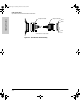
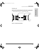
EIA-530
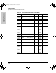
Figure A-3 shows the EIA-530 serial cable assembly, and E-4 lists the pinouts.
Arrows indicate signal direction: —> indicates DTE to DCE, and <— indicates
DCE to DTE.
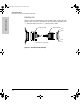
Auxiliary
Port (DTE)
RJ-45-to-RJ-45
Roll-Over Cable
RJ-45-to-DB-25
Modem Adapter
Modem
Signal RJ-45 Pin RJ-45 Pin DB-25 Pin Signal
RTS 1
a
a. Pin 1 is connected internally to Pin 8.
84 RTS
DTR 2 7 20 DTR
TxD 3 6 3 TxD
GND 4 5 7 GND
GND 5 4 7 GND
RxD 6 3 2 RxD
DSR 7 2 8 DCD
CTS 8
1
15 CTS
J3138.bk Page 5 Wednesday, March 18, 1998 6:07 PM