
Installation Manual


A-4
Cable Specifications
Console and Auxiliary Port Signals and Pinouts
Cable Specifications
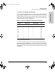
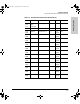
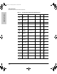
Table A-2. Console Port Signaling and Cabling Using a DB-25 Adapter
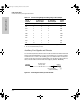
Auxiliary Port Signals and Pinouts
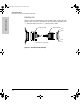
Use the thin, flat, RJ-45-to-RJ-45 roll-over cable and RJ-45-to-DB-25 male DCE
adapter (labeled “MODEM”) to connect the auxiliary port to a modem. Figure
A-2 shows how to connect the auxiliary port to a modem. Table A-3 lists the
pinouts for the asynchronous serial auxiliary port, the RJ-45-to-RJ-45 roll-over
cable, and the RJ-45-to-DB-25 male DCE adapter (labeled “MODEM”).
Figure A-2. Connecting the Auxiliary Port to a Modem
Console
Port (DTE)
a
a. You can use the same cabling to connect a console to the auxiliary port.
RJ-45-to-RJ-45
Roll-Over Cable
RJ-45-to-DB-25
Terminal Adapter
Console
Device
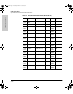
Signal RJ-45 Pin RJ-45 Pin DB-25 Pin Signal
RTS 1
b
b. Pin 1 is connected internally to Pin 8.
85 CTS
DTR 2 7 6 DSR
TxD 3 6 3 RxD
GND 4 5 7 GND
GND 5 4 7 GND
RxD 6 3 2 TxD
DSR 7 2 20 DTR
CTS 8
b
14 RTS
RJ-45-to-RJ-45
roll-over cable
RJ-45-to-DB-25 adapter
(labeled “MODEM”)
Modem
Router
H6094
J3138.bk Page 4 Wednesday, March 18, 1998 6:07 PM