
Installation Manual


ProCurve Secure Router Installation Guide Appendix A. Connector Pin Definitions
5990-3760 Copyright 2006 Hewlett-Packard Development Company, LP 45
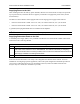
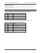
Table A-6. G.703 Connector Pinouts
Pin Name Description
1 R Transmit data toward the DTE
2 T Transmit data toward the DTE
3 — Unused
4 R1 Receive data from the DTE
5 T1 Receive data from the DTE
6-8 — Unused
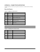
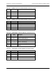
Table A-7. 1xSerial Interface and 8xSerial Wide Module Connector Pinouts
Serial Pin V.35 Pin X.21 Pin Description
1 P 2 Transmit data A (TD_A)
2 U N/A External transmit clock (ETC_A)
3 Y N/A Transmit clock A (TCLK_A)
4 V 6 Receive clock A (RCLK_A)
5 R 4 Receive data A (RD_A)
6 F N/A Data carrier detect A (DCD_A)
7 H N/A Data transmit ready A (DTR_A)
8 C 3 Request to send A (RTS_A)
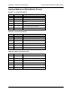
9 N/A 10 Request to send B (RTS_B)
V.11 only
10 N/A 12 Clear to send B (CTS_B)
V.11 only
11 D 5 Clear to send A (CTS_A)
12 E N/A Data set ready A (DSR_A)
13 K N/A Test mode A (TM_A)
14 S 9 Transmit data B (TD_B)
15 W N/A External transmit clock B (ETC_B)
16 AA N/A Transmit clock B (TCLK_B)
17 X 13 Receive clock B (RCLK_B)
18 T 11 Receive data B (RD_B)
19-25 N/A N/A Unused
26 B 8 Ground (GND)