
Installation Manual

ProCurve Secure Router Installation Guide Physical Description
5990-3760 Copyright 2006 Hewlett-Packard Development Company, LP 15
2. PHYSICAL DESCRIPTION
Reviewing the Front Panel Design
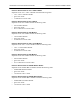
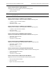
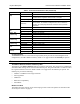
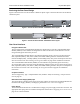
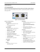
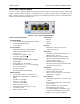
Figure 1 shows the ProCurve Secure Router 7102dl front panel. Figure 2 shows the
ProCurve Secure Router 7203dl front panel. The pictures show the chassis with modules installed.
Figure 1. ProCurve Secure Router 7102dl Front Panel Layout
Figure 2. ProCurve Secure Router 7203dl Front Panel Layout
Front Panel Switches, Interfaces, and LEDs
Table 1 describes the front panel LEDs.
Table 1. ProCurve Secure Router LEDs
LED Color Indicates that…
Power
Off
The AC power input is off. Fault LED flashes slowly if RPS backup
power is on.
Green (flashing)
Unit is powering up. On power-up, the Power LED flashes if self-test
fails.
Green (solid) Power is on and self-test passed.
Fault Off Operation is normal.
Orange (flashing)
A fault condition exists:
One or more cooling fans have failed.
AC power is not being received or internal primary AC/DC
converter has failed.
One or more option modules have failed.
Slot 1/Slot 2 -
Stat
Off No interface module is installed, or interface is administratively down.
Green (solid) Link is up and everything is operational.
Red (solid)
Current alarm condition is present on the WAN interface, or there is a
self-test failure. The LED illuminates if an interface is configured and in
the “no shutdown” condition, but a valid physical network connection
has not yet been established.
Yellow (solid) Unit is in test.
Console
Power
Fault
Eth 0/1
Eth 0/2
Stat Stat
Slots
12
Bkp Bkp
Tx Tx
Rx Rx
dl dl
ProCurve 7102dl
Secure Router
J8752A
LINK LED
ACTIVITY LED
Console
Power
Fault
Eth 0/1
Eth 0/2
Stat Stat
Slots
12
Bkp Bkp
Tx Tx
Rx Rx
Stat
3
Act
Test
dl dl
ProCurve 7203dl
Secure Router
J8753A
dl
wide