HP StorageWorks 70 Modular Smart Array User Guide This guide provides information about the HP StorageWorks 70 Modular Smart Array Enclosure. Installation, cabling, configuration, and troubleshooting procedures are included.
Legal and notice information © Copyright 2007, 2010 Hewlett-Packard Development Company, L.P. The information contained herein is subject to change without notice. The only warranties for HP products and services are set forth in the express warranty statements accompanying such products and services. Nothing herein should be construed as constituting an additional warranty. HP shall not be liable for technical or editorial errors or omissions contained herein. Microsoft and Windows are U.S.
Contents 1 Hardware features and LED descriptions ............................................... 6 Front panel components ............................................................................................................... 6 Front panel LEDs ......................................................................................................................... 6 Rear panel components ...............................................................................................................
5 Operation and management ............................................................. 31 Powering on disk enclosures ....................................................................................................... 31 Powering off disk enclosures ....................................................................................................... 32 Updating disk enclosure firmware ...............................................................................................
Preventing electrostatic discharge ................................................................................................ 51 Grounding methods to prevent electrostatic discharge .................................................................... 51 C Specifications .................................................................................. 53 Environmental specifications .......................................................................................................
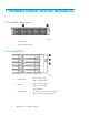
1 Hardware features and LED descriptions Front panel components 1 disk drive bays 2 Front unit ID (UID) module Front panel LEDs 1 Heartbeat LED 2 Fault LED Green = System activity Off = No system activity Amber = Fault condition Off = No fault condition Blue = Identified 3 UID button/LED Blue flashing = Active remote management Off = No active remote management 6 Hardware features and LED descriptions
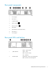
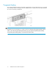
Rear panel components 1 Power supply 1 2 Fan module 1 3 7-segment display 4 SAS in connector 5 SAS out connector 6 I/O module 7 I/O module (for second I/O module) 8 Fan module 2 9 Power supply 2 Rear panel LEDs and buttons Green = System activity 1 I/O module LED Amber = Fault Off = No system activity Blue = Identified 2 UID button/LED Blue flashing = Active remote management Off = No active remote management 70 Modular Smart Array User Guide 7
Green = System activity 3 Heartbeat LED Amber = Fault Off = No system activity Green = Normal operation 4 Fan module LED Amber = Fault condition Off = Fan unseated form connector or failed 5 System fault LED 6 Power On/Standby button/system power LED Amber = Fault condition Off = No fault condition Green = On Amber = Standby (power present) Off = Off Green = Power turned on and power supply functioning properly Amber = Standby (auxiliary power present) Blinking amber = Power to this power supply n
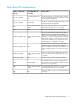
Disk drive LED combinations Online/activity LED (green) Fault/UID LED (amber/blue) On, off, or flashing Alternating amber and blue The drive has failed, or a predictive failure alert has been received for this drive; it also has been selected by a management application. On, off, or flashing Steadily blue The drive is operating normally, and it has been selected by a management application. On Amber, flashing regularly (1 Hz) A predictive failure alert has been received for this drive.
7-segment display The 7-segment display shows the box ID number assigned to the enclosure based on how it is connected to the controller. If there are multiple enclosures attached to the controller, the box ID number identifies the order in which they are attached.
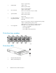
2 Deployment types The following types of deployments are supported: • Single domain In a single domain deployment, one path exists from the disk enclosure to the host. In a single domain deployment, only one I/O module in the disk enclosure is used • Dual domain In a dual domain deployment, two paths exist from the disk enclosure to the host. In a dual domain deployment, both I/O modules in the disk enclosure are used.
Deployment types
3 Installing the enclosure Environmental requirements When installing the enclosure in a rack, select a location that meets the environmental standards described in this section. Space and airflow requirements To allow for servicing and adequate airflow, observe the following space and airflow requirements when deciding where to install a rack: • Leave minimum clearance of 63.5 cm (25 in) in front of the rack. • Leave minimum clearance of 76.2 cm (30 in) behind the rack. • Leave minimum clearance of 121.
CAUTION: If a third-party rack is used, observe the following additional requirements to ensure adequate airflow and to prevent damage to the equipment: • Front and rear doors—If the 42U rack includes closing front and rear doors, you must allow 5,350 sq cm (830 sq in) of holes evenly distributed from top to bottom to permit adequate airflow (equivalent to the required 64 percent open area for ventilation).
• Balance the enclosure power load between available AC supply branch circuits. • Do not allow the overall system AC current load to exceed 80 percent of the branch circuit AC current rating. • Do not use common power outlet strips for this equipment. • Provide a separate electrical circuit for each power supply in the enclosure. Electrical grounding requirements The enclosure must be grounded properly for proper operation and safety.
WARNING! To reduce the risk of personal injury or equipment damage when unloading a rack: • At least two people are needed to safely unload the rack from the pallet. An empty 42U rack can weigh as much as 115 kg (253 lb), can stand more than 2.1 m (7 ft) tall, and may become unstable when being moved on its casters. • Never stand in front of the rack when it is rolling down the ramp from the pallet. Always handle the rack from both sides.
Converting rails for round-hole racks The rack rails ship configured for square-hole racks. To convert the rack rails for use in a round-hole rack: 1. 2. 3. Locate the bag of miscellaneous hardware that ships with the rack rails. Locate the eight round-hole pins. Use a No. 2 Phillips screwdriver to remove the standard pins from the front and back ends of the rail. 4. Install four round-hole pins into the rail. 5. Repeat steps 3 and 4 for the second rail.
Installing the enclosure into the rack To install the enclosure into a rack: 1. Secure the front end of the rails to the rack. IMPORTANT: Do not remove the pins from the ends of the rack rails unless you are converting the rails for use in round-hole racks. These load-bearing pins are designed to fit through the holes without being removed. IMPORTANT: Be sure that the scissor-type locking latches engage the rack fully when the pins extend through the holes marked with the template.
3. 4. 5. Slide the chassis into the rack. Use the thumbscrews on the front of the chassis to secure it to the rack. Use the shipping bracket to secure the enclosure for shipping: IMPORTANT: Use of the shipping bracket is required only when the rack is shipped with the enclosure installed. a. b. c. Loosen the thumbscrew on the shipping bracket. Slide the shipping bracket forward until it engages the chassis. Tighten the thumbscrew.
• Follow industry-standard practices when handling disk drives. Internal storage media can be damaged when drives are shaken, dropped, or roughly placed on a work surface. • When installing a disk drive, press firmly to make sure the drive is fully seated in the drive bay and then close the latch handle. • When removing a disk drive, press the release button and pull the drive only slightly out of the enclosure.
2. Press the latch and slide it to the right to disengage the lever (1), and then open the lever (2). Make sure that the lever is in the fully opened position before inserting the drive into the bay. 3. Slide the disk drive into the bay (1), pressing firmly on the drive to seat it.
Installing SAS controllers or controller enclosures When installing controllers or controller enclosures, be sure to do the following. • Record information about the controller or controller enclosure that will connect to the disk enclosure. • Depending on your deployment, do one of the following: • For server connect deployments, install one or more Smart Array controllers in the server that will access the disk enclosure.
Connecting SAS cables and power cords After installing the enclosure in a rack, connect the SAS cables and power cords. Cabling best practices • Use the shortest possible cable between devices. Shorter cables are easier to manage and route along the back of the rack. In addition, shorter cables reduce the possibility of signal degradation that might occur over longer distances.
Connecting SAS cables to additional disk enclosures To connect an additional disk enclosure to a disk enclosure that is already connected to the server or controller enclosure, use a supported SAS cable. NOTE: The left connector on the I/O module is for input from the server or controller enclosure. The right connector on the I/O module is for output to an additional enclosure. See the icons on the cables and the enclosure to assist in proper connection.
To protect the system from power-failure-related downtime, each disk enclosure ships standard with a redundant power supply. Depending how you connect the power supplies to the power source, you can eliminate downtime caused by power-related failures. Connection Method Disk enclosure power supplies connected to: one power source Level of Protection Protects you from downtime when one of the disk enclosure power supplies fails.
Powering on the disk enclosure After disk enclosures are physically installed and cabled, power on all devices and verify that they are operating properly. Power on best practices Observe the following best practices before powering on the disk enclosure for the first time: • Complete the server, controller, or controller enclosure installation. For more information, see the server, controller, or controller enclosure user documents. • Install the disk enclosures.
Verifying the operating status of the disk enclosures To verify that the disk enclosures and disk drives are operating properly, view the enclosure and disk drive LEDs and compare them with the patterns described in Chapter 1. If LED patterns are not as expected, check cable connections between the devices, check the availability of your power source, review the installation procedures, and remove and reinsert the module.
Installing the enclosure
4 Configuring the enclosure Configuration overview Regardless of the operating system environment or software tool used to configure the disk enclosure, the following tasks must be completed: • Updating controller or controller enclosure firmware or drivers. Instructions are included with the controller or controller enclosure. • Updating disk enclosure firmware. Instructions are included with the firmware. For more information, see “Updating disk enclosure firmware” on page 32.
Configuring the enclosure
5 Operation and management Included topics: • Powering on disk enclosures, page 31 • Powering off disk enclosures, page 32 • Updating disk enclosure firmware, page 32 Powering on disk enclosures IMPORTANT: Always power on disk enclosures before controller enclosures and servers. This ensures that servers, during the discovery process, identify the enclosures and installed disk drives as operational devices. 1. 2. 3. Apply power to each uninterruptible power supply (UPS).
Powering off disk enclosures IMPORTANT: Always power off disk enclosures after controller enclosures and servers. IMPORTANT: When installing a hot-pluggable component, such as a disk drive, it is not necessary to power down the enclosure. To power off a disk enclosure: 1. Power off any attached servers. For more information, see the server documentation. 2. Power off the controller enclosure (if included in the configuration.) For more information, see the controller enclosure documentation. 3.
6 Troubleshooting When the enclosure does not start If the enclosure does not power up: 1. 2. 3. Verify that the server, monitor, and enclosure are plugged in. Verify that the server and monitor are working. Verify that the power source is working: a. Ensure that the Power On/Standby button was pressed firmly and held for approximately three seconds. b. View the system power LED on the back panel (see Rear panel LEDs and buttons). 4.
Diagnostic steps Are the power supply/fan module LEDs green? Answer Possible Reasons Possible Solutions • Be sure that the power cord is connected to the power supply. • The power cords are not connected or AC power is not available. No • The power supply may not be inserted properly, it may have a damaged connector, or it may have failed. • The system midplane may need to be replaced. Yes System is functioning properly. • Be sure that the power supply is undamaged and is fully seated.
• CPQONLIN identifies failed drives in a NetWare environment. For additional information about diagnosing disk drive problems, see the HP ProLiant Servers Troubleshooting Guide. CAUTION: Sometimes, a drive that has previously failed may seem to be operational after the system is power-cycled or, for a hot-pluggable drive, after the drive has been removed and reinserted. However, continued use of such marginal drives may eventually result in data loss. Replace the marginal drive as soon as possible.
3. Power up the enclosure (see Powering on disk enclosures). NOTE: In some cases, a marginal drive is operational long enough to allow backups of important files. 4. Make copies of important data, if possible. 5. Replace any failed drives. Read Factors to consider before replacing hard drives before replacing the failed disk drives.
or rebuild. If fault tolerance is compromised, this data cannot be reconstructed and is likely to be permanently lost. If another drive in the array fails while fault tolerance is unavailable during rebuild, a fatal system error may occur, and all data on the array is then lost. In exceptional cases, however, failure of another drive need not lead to a fatal system error. These exceptions include: • Failure after activation of a spare drive.
Failed drives or interim recovery mode If a drive fails and hardware fault tolerance is enabled, operation continues. Do the following: 1. Replace the drive as soon as possible. 2. Select a logical drive. 3. Press the F3 key to monitor to the status of drive recovery. Drive status messages include: • Interim Recovery: The logical drive is operating, but a failed drive has not been replaced. Replace the drive as soon as possible. • Ready for Recovery: The logical drives are queued for recovery.
NOTE: NetWare cannot detect a single physical drive failure when using hardware-based fault tolerance. NetWare determines that the data is still valid and accessible during the rebuilding process. However, the driver knows that a physical drive has failed. A message is printed on the console notifying the user that a physical drive is in a degraded state. CPQONLIN also shows that the drive has failed.
Troubleshooting
7 Support and other resources Contacting HP Before you contact HP Be sure to have the following information available before you call or contact HP: • Technical support registration number (if applicable) • Product serial number • Product model name and number • • • • • Product identification number Applicable error message Add-on boards or hardware Third-party hardware or software Operating system type and revision level HP contact information For the name of the nearest HP authorized reseller: • See the
Documentation feedback HP welcomes your feedback. To make comments and suggestions about product documentation, please send a message to storagedocsFeedback@hp.com. All submissions become the property of HP. Related information Websites • HP: http://www.hp.com • HP storage: http://www.hp.com/go/storage • HP support: http://www.hp.com/support • HP manuals: http://www.hp.com/support/manuals • HP downloads: http://www.hp.
CAUTION: Indicates that failure to follow directions could result in damage to equipment or data. IMPORTANT: Provides clarifying information or specific instructions. NOTE: Provides additional information. TIP: Provides helpful hints and shortcuts. Customer self repair HP customer self repair (CSR) programs allow you to repair your StorageWorks product. If a CSR part needs replacing, HP ships the part directly to you so that you can install it at your convenience. Some parts do not qualify for CSR.
Support and other resources
A Regulatory compliance notices Regulatory compliance identification numbers For the purpose of regulatory compliance certifications and identification, this product has been assigned a unique regulatory model number. The regulatory model number can be found on the product nameplate label, along with all required approval markings and information. When requesting compliance information for this product, always see this regulatory model number.
interference will not occur in a particular installation. If this equipment does cause harmful interference to radio or television reception, which can be determined by turning the equipment off and on, the user is encouraged to try to correct the interference by one or more of the following measures: • Reorient or relocate the receiving antenna. • Increase the separation between the equipment and receiver.
This Class B digital apparatus meets all requirements of the Canadian Interference-Causing Equipment Regulations. Cet appareil numérique de la classe B respecte toutes les exigences du Règlement sur le matériel brouilleur du Canada. European Union regulatory notice This product complies with the following EU Directives: • Low Voltage Directive 73/23/EEC • EMC Directive 89/336/EEC CE Compliance of this product is valid only if powered with the correct HP-provided and CE marked AC adapter.
Frequency availability for 802.11a or 802.11h Wireless LAN is not currently harmonized throughout the European Union. For compliance requirements, users should verify with their supplier, local HP office or Telecommunications authority. Disposal of waste equipment by users in private households in the European Union This symbol on the product or on its packaging indicates that this product must not be disposed of with your other household waste.
Korean notice Class A equipment Class B equipment Power cord statement for Japan 70 Modular Smart Array User Guide 49
Regulatory compliance notices
B Electrostatic discharge Preventing electrostatic discharge To prevent damaging the system, be aware of the precautions you need to follow when setting up the system or handling parts. A discharge of static electricity from a finger or other conductor may damage system boards or other static-sensitive devices. This type of damage may reduce the life expectancy of the device. To prevent electrostatic damage: • Avoid hand contact by transporting and storing products in static-safe containers.
Electrostatic discharge
C Specifications Environmental specifications Specification Value Temperature range Operating1 Storage 10°C to 35°C (50°F to 95°F) Maximum rate of change is 10º C/Hr (50º F/Hr) -30°C to 60°C (-22°F to 140°F) Maximum rate of change is 20º C/Hr (68º F/Hr) Relative humidity2 10% to 90% relative humidity (Rh) Operating 28º C (82.4º F) maximum wet bulb temperature non-condensing 5% to 95% relative humidity (Rh) Storage 38.7º C (101.
Specification Value Width 44.80 cm (17.64 in) Weight (maximum) 21.77 kg (48 lb) Weight (no drives installed) 15.
Acronyms and Abbreviations ACU Array Configuration Utility ADG Advanced Data Guarding (also known as RAID 6) ADU Array Diagnostics Utility CSA Canadian Standards Association HBA host bus adapter IEC International Electrotechnical Commission IEEE Institute of Electrical and Electronics Engineers IML Integrated Management Log MSA Modular Smart Array MSA70 HP Storage Works 70 Modular Smart Array Enclosure NECA National Electrical Code NEMA National Electrical Manufacturers Association N
Acronyms and Abbreviations
Index A airflow requirements, 13 automatic data recovery (rebuild), 36, 37 B best practices cabling, 23 power sources, 25 powering on, 26 BSMI notice, 48 C cables, 46 best practices, 23 cable management considerations, 23 connecting cascaded enclosures, 24 connecting power cords, 25 connecting to the controller, 23 cables, supported, 23 cabling guidelines, 23 Canadian notice, 46 Class A equipment, 46 Class B equipment, 46 cascaded disk enclosures, 24 Class A equipment Canadian n notice, 46 Federal Communi
electrostatic discharge, 51 grounding methods, 51 preventing, 51 enclosure cabling, 23 configuring, 29 installing into rack, 18 environmental requirements, 13 European Union regulatory notice, 47 F failure of disk drive during rebuild, 37 fault tolerance, compromised, 35 FCC See Federal Communications Commission notice Federal Communications Commission notice, 45 Class A equipment, 45 Class B equipment, 45 FCC rating label, 45 Modifications, 46 front panel components, 6 LEDs, 6 G grounding methods, 51 gro
rack warnings, 15 rear panel buttons, 7 components, 7 LEDs, 7 rebuild description of, 36 time required for, 37 redundant power cables, 25 regulatory compliance notices, 45 requirements airflow, 13 electrical grounding, 15 environmental, 13 power, 14 space, 13 temperature, 14 V verifying the status of disk enclosure, 27 W warnings rack stability, 43 warnings, rack, 15 websites customer self repair, 43 HP , HP Subscriber's Choice for Business, 41 S server preparing for use with disk enclosure, 22 shipping